
The MAIN JOURNAL for POWER GRID SPECIALISTS in RUSSIA
38
diagnosis and monitoring
Th
ermoSensor.
Monitoring of
the State of the Electrical Equipment
Сontact System in 0.4-20 kV Networks
Trends of modern power engineering are focused on digital network development.
One of the tasks of PJSC ROSSETI Concept of Networks Digitalization for 2018-2030
is the implementation of electrical network equipment capable to continuous condi-
tion monitoring and defects identi
fi
cation.
ThermoSensor remote control
system is designed for contact sys-
tem of 6-10 kV Package Outdoor
Switchgear (POS) cubicles, equip-
ment of 6-20 kV Packaged Trans-
former Substations (PTS) and 0.4 kV
switchgears. The system is fully
compatible with PJSC ROSSETI
target technological model of digital
network and provides with possibil-
ity to determine local emergency
overheating of electrical equipment
in continuous mode with subse-
quent automatic signal sending to
the dispatcher console.
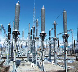
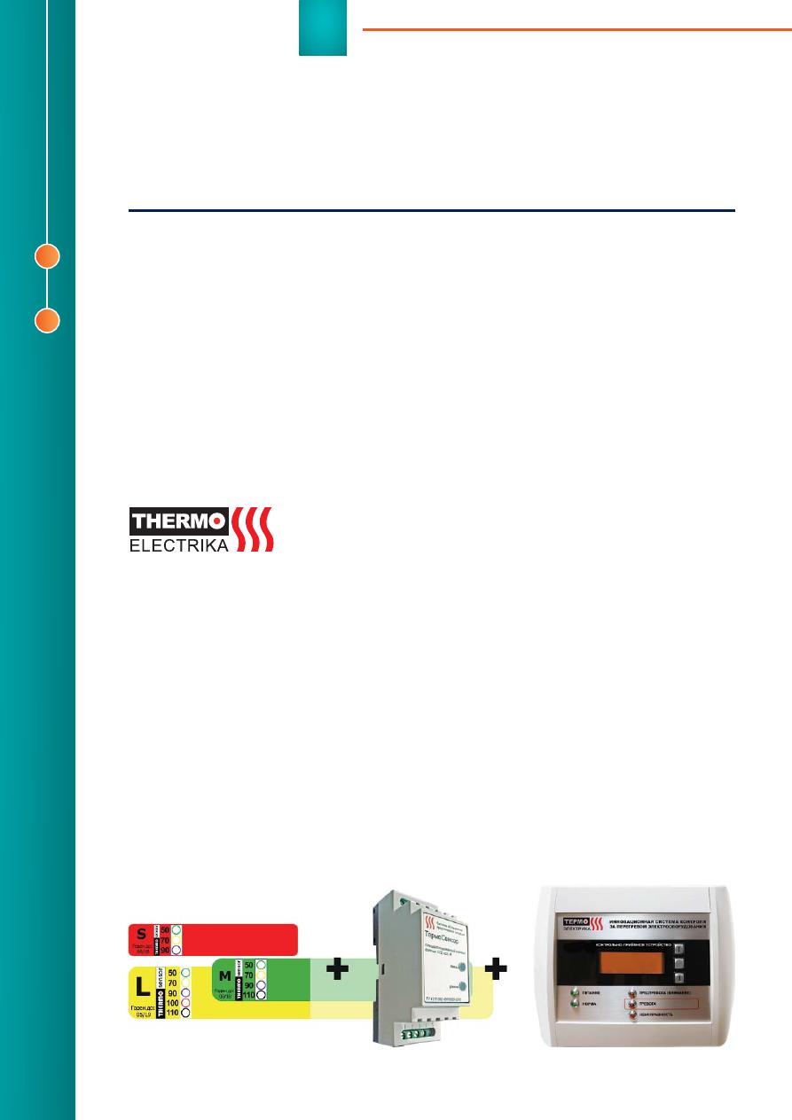
ThermoSensor system (Figure 1)
consists of gas-generating stickers,
a gas sensor and checking and re-
ceiving device (CRD). Stickers are
placed on the contact connections
(CC). When heated, the stickers
change the color and generate sig-
nal gas, which is captured by the
sensor. The overheating signal is
transmitted via CAN bus or Modbus
RTU (RS485) to the CRD, then to
the workstation (WKS), central con-
trol room (CCR), digital communica-
tion center (DCC) and
fi
re alarm sys-
tem. In addition, the sensor beeps.
Also, automatic disconnection of
protected object is possible.
ThermoSensor system provides
fault-
fi
nding before an emergency
shutdown and
fi
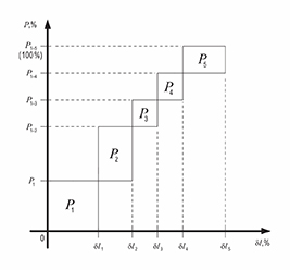
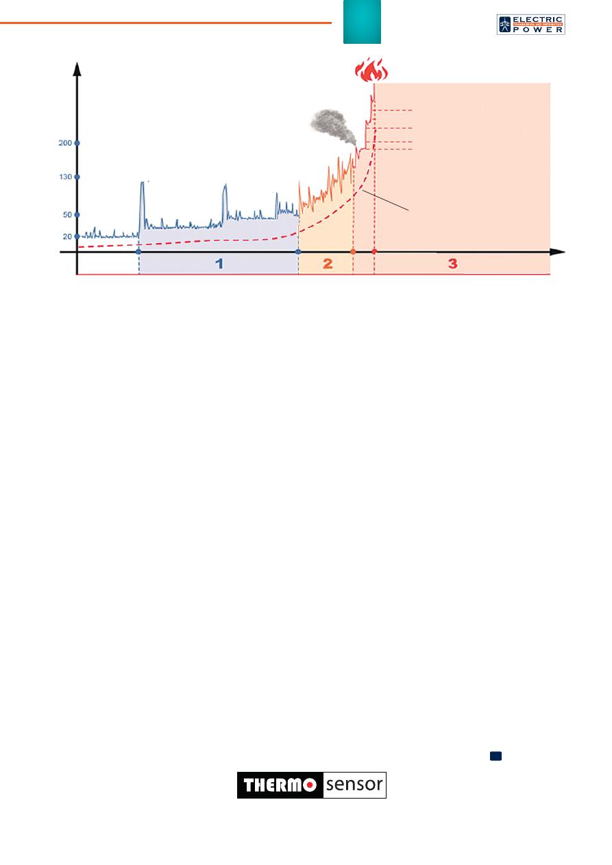
re occur. Figure 2
shows CC heating chronology.
Segment no. 1 on the life cycle line
of electrical equipment demon-
strates time period when CC emer-
gency heating occurs (for example,
as a result of short-circuit currents).
On this segment, planned infrared
control can detect CC heating only
when
fl
owing currents are close
to the maximum. After some time,
the defect grows. Line no. 2 shows
stable CC heating, which is eas-
ily detected by thermal imagers or
pyrometers regardless of the load.
On this segment, signi
fi
cant deg-
radation processes take place in
CC (those processes characterize
CC reliability). During any subse-
quent network disturbance, as well
as long-term day-to-day opera-
tion, this CC can be damaged and
go to the third phase (line no. 3 in
Figure 2). When emergency tem-
peratures are reached, the CC is
destroyed regardless of the load.
When this happens emergency
shutdown occurs and leads to
fi
re
in some cases.
ThermoSensor system auto-
matically
fi
xes single local CC over-
heating up to 80-120º
С
, and trans-
mits a fault signal long before an
emergency or
fi
re occur.
ThermoSensor system advan-
tages in comparison with classic
Figure 1. ThermoSensor innovative system for monitoring of electrical equipment overheating: a) gas-generating
stickers with heat-indicating scale; b) specialized gas sensor; c) checking and receiving device
a)
b)
c)
ThermoElectrika, LLC
Russian Federation,
Moscow, Skolkovo
Innovation Center,
Bolshoy boulevard, 42,
bld. 1, room no. 754,
Tel.: +7 (495) 231-92-99,
info@thermoelectrika.com
www.thermoelectrika.com
Svetlana
VYSOGORETS,
Ph.D., Strategic
Development Director of
ThermoElectrika, LLC
Aleksey LESIV,
Business Development
Director of Thermo-
Electrika, LLC
39
diagnostics of distribution network
electrical equipment are:
• costs saving for expensive ther-
mal imaging;
• inspection personnel drawdown;
• continuous electrical equipment
monitoring without inspection in-
terruptions (including monitoring
during peak loads). It should be
pointed that CC resistance mea-
surement or CC heating control
with pyrometers give a possibi-
lity to assess technical state at
given time under given condi-
tions. With that,
fi
rm prediction
of obsolete electrical equipment
reliability is a systemic scienti
fi
c
and technical problem;
• ability to control nodes which are
not suitable for thermal imaging;
• absence of necessity to discon-
nect electrical equipment for in-
spection purposes. As a result,
there is no need for additional
switching and special modes in
electrical network. It increases di-
agnosis accuracy and ef
fi
ciency;
• ef
fi
ciency upgrade and auto-
matic transmission of data on
detected defect to the customer
or operational personnel and
hence cutting time for remedial
work organization;
• improvement of diagnosing ef-
fi
ciency for electrical equipment
with excess operational life-
time and reducing operational
costs for maintenance. The
frequency of technical diagnos-
tics approved by standards and
technical documentation has
to provide relative reliability of
defects detection in electrical
equipment within its rated life-
time. Defects in worn-out elec-
trical equipment grow much
faster in comparison with equip-
ment working for rated lifetime.
Due to this fact it can be ne-
cessary to shorten the time be-
tween scheduled diagnostics of
obsolete electrical equipment,
to reduce overhaul period and,
as a result, to increase operat-
ing costs;
• ThermoSensor system provides
observability of electrical net-
work, and is a self-diagnosis sys-
tem element for determination
of contact system conditions.
The development of data trans-
fer system from ThermoSensor
CRD to utility’s network manage-
ment system gives a possibility
to provide intellectual adapta-
tion of network operation modes
depending on network technical
conditions (as an example of
such adaptation is interdiction to
connect load to cubicles where
emergency overheating is de-
tected);
• integration of the ThermoSensor
system in post-accident monitor-
ing system (PAMS) improves ac-
curacy of real technical condition
index calculation. The improve-
ment of the system for collecting
and analyzing ThermoSensor
operation results gives a chance
to evaluate repair work ef
fi
cien-
cy. Among the estimated factors
are materials and technologies
used, the quality of repair crews
operation, and distribution net-
work elements deterioration.
Thus, the ThermoSensor sys-
tem provides effective control of
equipment reliability taking into ac-
count the revealed shortcomings
of the classical diagnostic system.
The technical result of the Thermo-
Sensor system implementation is
a reduction of emergencies in elec-
trical networks and an increase of
operation ef
fi
ciency.
Experimental operation of the
ThermoSensor system and its im-
plementation as a pilot project are
already conducted at a number of
major Russian enterprises. Ther-
moSensor system ef
fi
ciency was
proved by full-scale tests carried out
at the facilities of PJSC "MOESK",
LLC "ABB" (tests in 6-25 kV switch-
gear cubicles) and JSC "UNECO"
(tests in RM6 cubicles).
ThermoSensor system produc-
tion is located in the Russian Fede-
ration. It is protected by patents
and has the necessary certi
fi
ca-
tion, including certi
fi
cate of FGBU
VNIIPO of EMERCOM of Russia.
The ThermoSensor system is the
cheapest technology in the world,
characterized by simple installation
and maintenance.
Р
Figure 2. Heating chronology of contact connection (CC)
CC temperature, °
С
Ignition
Life cycle
Existing solutions:
The line of CC thermal
defect development during
the life cycle
Thermal indicators
Smoke indicators
Aspirating systems
Gas detectors
ThermoSensor system is a Russian
innovative solution for gas analytical
control of CC heating of distribution
network electrical equipment. The system has competitive advantages in
comparison with technologies for CC overheating detection and has no ana-
logues in the world.
47th CIGRE Session
Special issue, August 2018
Оригинал статьи: ThermoSensor. Monitoring of the State of the Electrical Equipment Сontact System in 0.4-20 kV Networks
Trends of modern power engineering are focused on digital network development. One of the tasks of PJSC ROSSETI Concept of Networks Digitalization for 2018-2030 is the implementation of electrical network equipment capable to continuous condition monitoring and defects identification.