
The MAIN JOURNAL for POWER GRID SPECIALISTS in RUSSIA
3 - 6 J U N E 2 0 1 9
MADRID, SPAIN
The MAIN JOURNAL for POWER GRID SPECIALISTS in RUSSIA
3 - 6 J U N E 2 0 1 9
MADRID, SPAIN
1
8
s
m
a
r
t
g
r
id
smart grid
Th
e First
Digital Substation
in the Moscow Region
OVERALL DESIGN SOLUTIONS REGARDING TO SUBSTATION
PRIMARY EQUIPMENT AND ITS MONITORING SYSTEMS
110 kV SF6 gas insulated switchgear
(GIS) of the substation is performed us-
ing "two main busbars" scheme. It is de-
signed for connecting four transmission
lines, two transformers and a busbar
coupler. 110 kV SF6 GIS produced by
"VO "Elektroapparat" JSC is equipped
with advanced monitoring system, in-
cluding:
– partial discharge monitoring system
(designed for monitoring 110 kV GIS
insulation condition and determining
defect type and location through
embedded expert system);
– system for monitoring circuit break-
ers condition (designed to calculate
mechanical wear of circuit breakers
and commutation life of the contact
elements);
– monitoring system of feeders current
and buses voltage as well as moni-
toring switching devices position and
condition.
Two 80 MVA power transformers
manufactured by "Togliatti Transform-
er", LLC are equipped with monitoring
system including the following:
– monitoring system of critical dissipa-
tion (control of transformer oil level);
– online monitoring of high-voltage
bushings;
– control of transformer windings cur-
rent and OLTC position (OLTC —
on-load tap changing);
– chromatic monitoring of the trans-
former oil condition (to fi nd a defect
in transformer insulation initially and
to predict the technical condition).
110 kV GIS and transformers
monitoring system, controlling about
400 signals and measurements in to-
tal, is used for automatic assessment
of the substation equipment technical
condition, incipient failure detection
and prediction, forecasting and simu-
lating load capacitance and equipment
remaining life.
As a result, the system provides cut-
ting of operational costs for equipment
maintenance and repair, as well as
improving the effi ciency of equipment
monitoring.
It is worth noting that low-resistance
neutral grounding of 20 kV power
transformer windings can signifi cantly
increase the safety of personnel and
popu lation during one-phase short cir-
cuit in 20 kV distribution network.
OVERALL DESIGN SOLUTIONS REGARDING TO AUTOMATED
PROCESS CONTROL SYSTEM AND RELAY PROTECTION
AND AUTOMATION SYSTEM
The main unique feature of 110 kV "Med-
vedevskaya" digital substation is a mark-
edly diff erent structure of automated pro-
cess control system and relay protection
and automation system in comparison
with traditional facilities.
Martikhin
А
.Y.,
Head of Relay Protection and Automation Department of Moscow
High-voltage Networks — branch of PJSC "MOESK"
Rybin I.S.,
Deputy Head of Relay Protection and Automation Department of Moscow
High-voltage Networks — branch of PJSC "MOESK"
Guriev
А
.V.,
Chief Project Engineer of EKRA Research and Production Enterprise Ltd.
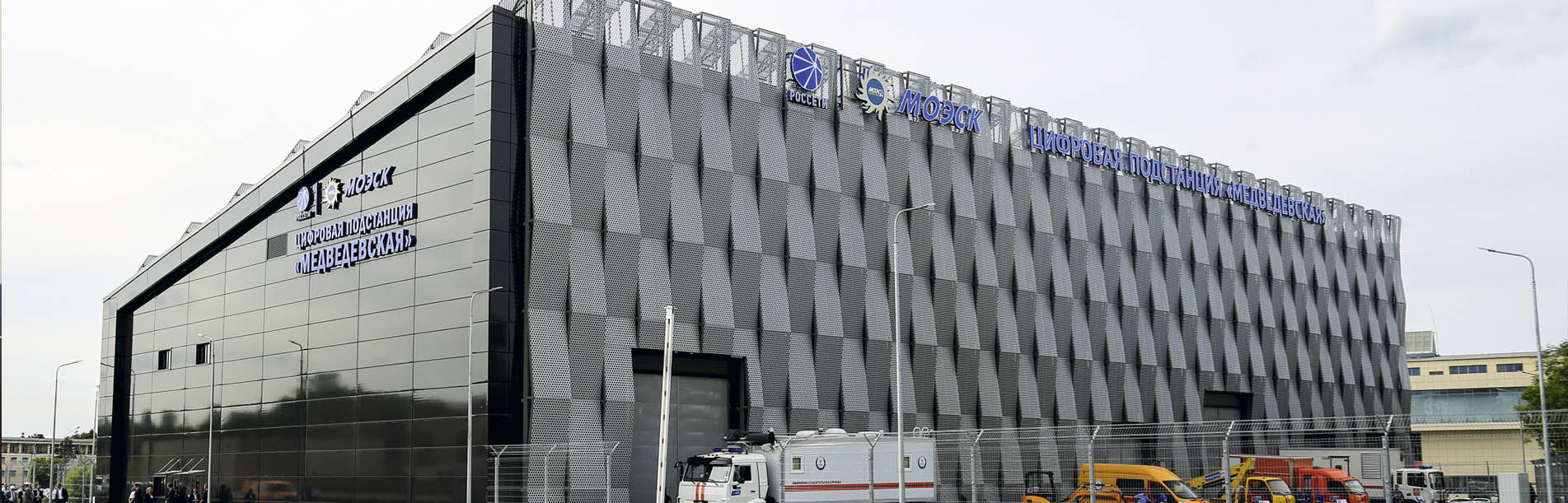
In May 2018 the 110 kV "Medvedevskaya" substation was brought
into operation in Moscow High-voltage Networks (a branch of
PJSC “MOESK”). It is the
fi
rst digital substation in the Moscow
region. This paper presents its key features and differences from
substations where traditional technologies are applied.
1
9
The function of relay protection
and automation equipment is per-
formed by BE2502 and BE2704
microprocessing terminals manu-
factured by EKRA Research and
Production Enterprise Ltd. Data ac-
quisition and transmission system
of the substation is made in accor-
dance with IEC 61850 requirements
and is divided into three subsystems
(in fact, local area networks formed
by routers and communication optic
fi ber cables).
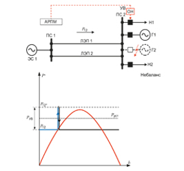
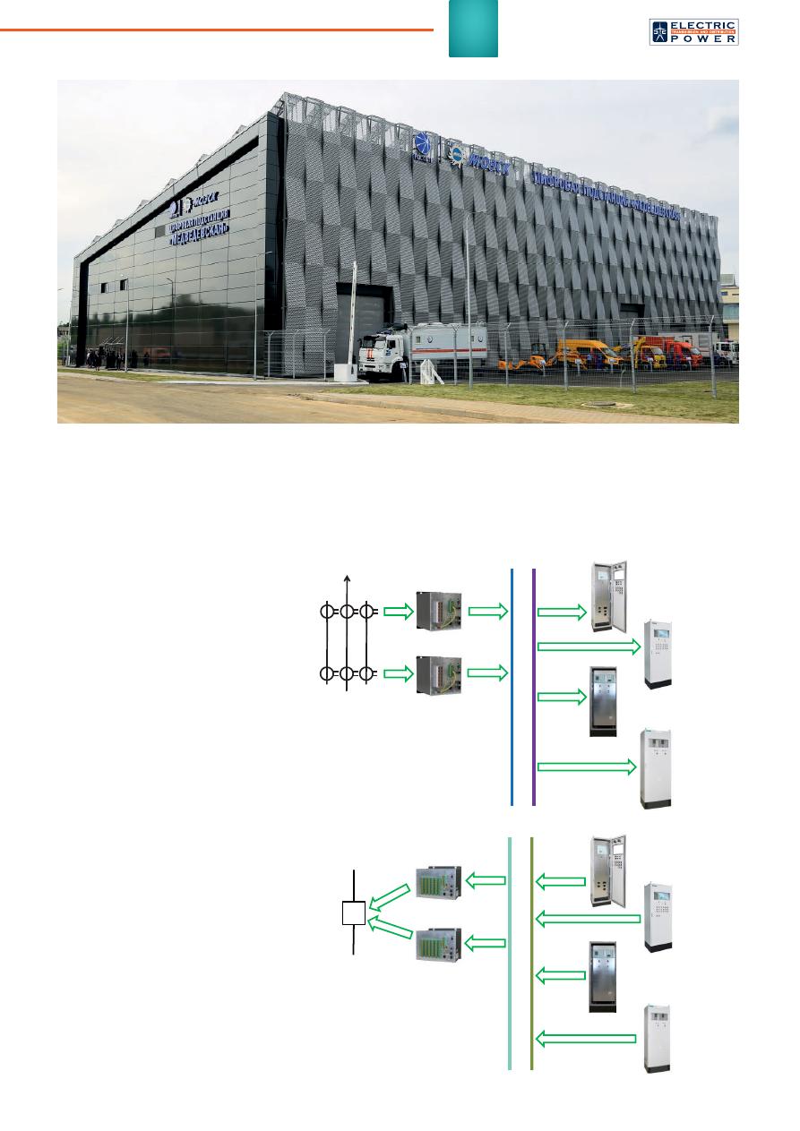
Analog data transmission from
the primary measuring equipment
(voltage and current transformers)
is performed through the "process
bus" in accordance with IEC 61850-
9.2LE (Figure 1).
Current and voltage magnitudes
measured by traditional electromag-
netic voltage and current transform-
ers are digitized by interface devices
and transmitted as Sampled Values
signals to the "process bus". Any re-
lay protection and automation equip-
ment can obtain these measuring
data when required.
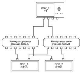
Digital signals between relay
protection and automation devices
(Figure 2), as well as signals from
relay protection devices to switching
devices are transmitted via the "data
bus" in GOOSE (Generic Object Ori-
ented Substation Events) message
format. These signals can be also
received and processed by any de-
vice capable to read them.
Finally, signals intended for au-
tomated process control system
AMU1
ТА1
ТА2
AMU2
Process bus (IEC 61850-9.2LE)
Main
protection
Back-up
protection
Circuit
breaker fail
protection
Differential
busbar
protection
DMU1
110 kV
circuit
breaker
DMU2
Substation busbar (IEC 61850-8.1)
Main
protection
Back-up
protection
Circuit
breaker fail
protection
Differential
busbar
protection
Fug. 2. Substation busbar
with data transmission according
to IEC 61850-8.1
Fug. 1. "Process bus" with
data transmission according
to IEC 61850-9.2LE
operation and its connection with
relay protection and automation
system are transmitted through
a special data bus in the MMS
format (Manufacturing Message
Specifi cation).
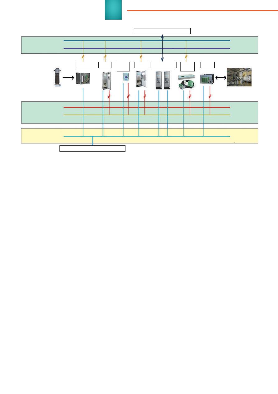
Time server is used for ensur-
ing coordinated functioning of data
buses based on PRP. Time synchro-
nization is performed via the PTPv2
protocol. Separate package of emer-
gency events registration is used for
The 25th CIRED Session
Special issue, June 2019
20
digital signals registration and moni-
toring (SV, GOOSE, MMS). Thus, the
concept of using technological infor-
mation exchange protocols in accor-
dance with IEC 61850 (Figure 3) is
fully implemented in 110 kV "Medve-
devskaya" substation.
As we can see, the fundamental
structural diff erence of such a net-
work is the connection between de-
vices via data buses instead of Peer-
to-Peer connection.
Moreover, the full signal separa-
tion of relay protection and automa-
tion system and automated process
control system has been applied.
This decision was made taking into
account the current organization
structure of operating company and
segregation of responsibility zones
of relay protection and automation
department and automated process
control system department. Besides,
the decision concerning full signal
separation provides an unobvious
advantage: relay circuits are all-
insulated from external information
networks. In this regard, special in-
formation security issues and special
hardware and software data security
of substation key elements were not
required during substation design
and commis sioning.
The functions of relay protection
and automation system are totally
traditional. The selection of protec-
tion functions is executed based on
PJSC "MOESK" requirements. The
implementation of relay protection
based on digital local computer net-
works has little in common with the
usual way of relay protection op-
eration (with a big number of copper
connections).
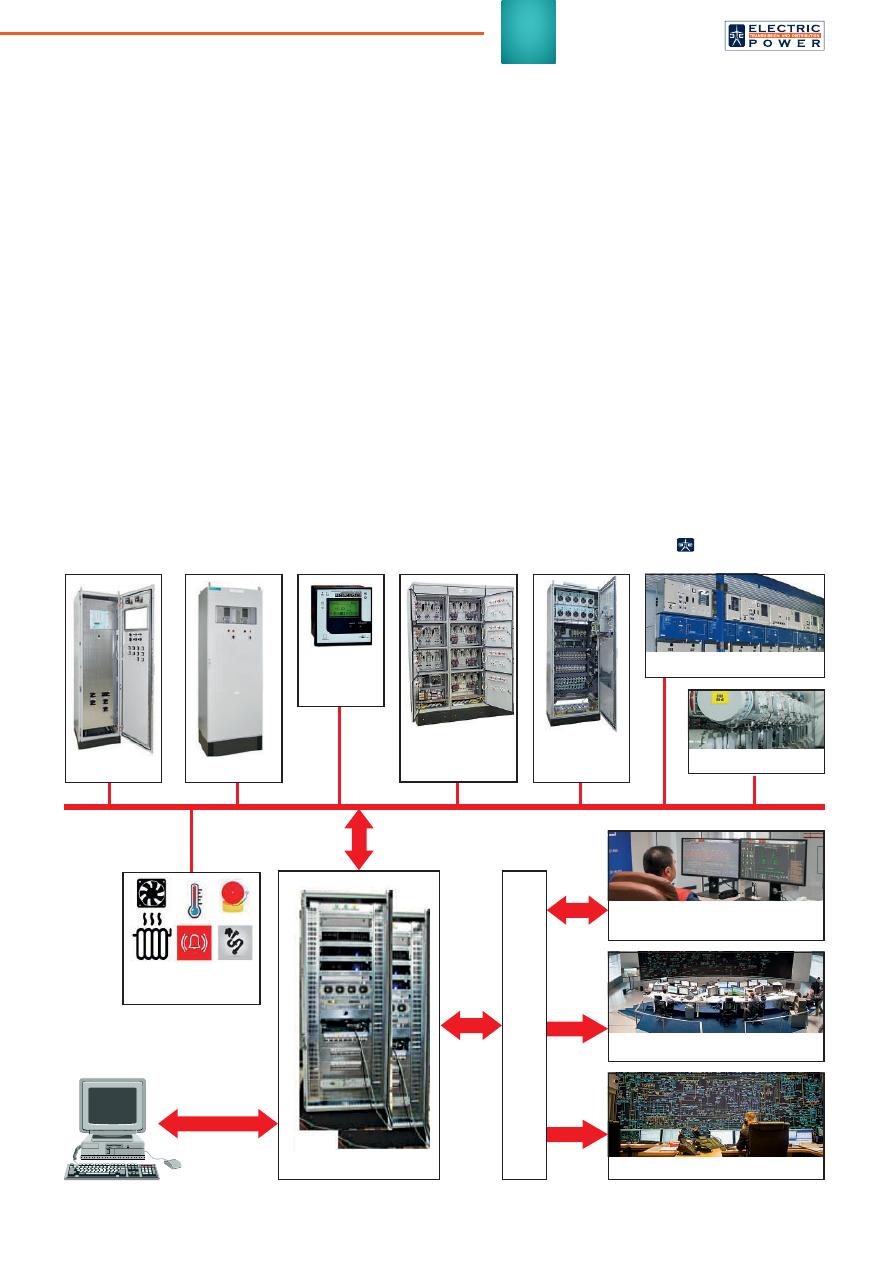
The automated process control
system of the substation (Figure 4)
is executed based on the EVICON
software and hardware. Herewith,
automated process control system
and automatic remote control are in-
extricably linked. These subsystems
are usually separated in the tradi-
tional substations. Single test and
self-diagnostics system of EVICON
software and hardware as well as
communication hubs and communi-
cations links (commutation switches
and optical fi ber communication
lines) provide reliable equipment op-
eration. This approach allowed engi-
neers to cut substantially the costs
of equipment used for collecting
and processing of primary analog
and digital signals. At the same time
separated servers of automated pro-
cess control system and automatic
remote control eliminate the risk (at
failure) of losing substation observ-
ability and controllability.
The automated process control
system and automatic remote control
in "Medvedevskaya" substation are
designed to complete the following
tasks:
– maintenance of online database
related to operation modes and
condition of substation equip-
ment;
– visualization and control of cur-
rent mode parameters (key single
line diagram, condition of substa-
tion electric equipment);
– execution of prealarm and alarm
system functions;
– remote and local control of prima-
ry equipment (power transform-
ers, switching devices, etc.);
– data reporting to the operations
control centers of the Moscow
Regional Dispatching Offi ce,
network control center of MOESK
and Moscow High-voltage Net-
works through standard protocols
(IEC 60870-5-104);
– data backup and information stor-
age;
– ensuring information security of
automated process control sys-
tem;
– preparation of reporting docu-
ments.
DIGITAL SUBSTATION
PROJECT ADVANTAGES
Afore-mentioned principles of relay
protection operation in the substa-
tion have the following advantages:
1. Cutting the costs for equipment
maintenance due to advanced
diagnostics and monitoring sys-
tem of primary equipment, au-
tomated process control system
equipment and relay protection
and automation equipment.
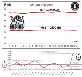
Fig. 3. Data exchange network of 110 kV "Medvedevskaya" digital substation
20 kV
RPA
Dispatching control
Substation technological systems
Process bus
(IEC 61850-9.2LE)
Relay
protection and
automation
Relay
protection and
automation
Substation busbar
no. 1 GOOSE
(IEC 61850-8.1)
Substation busbar
no. 2 MMS
(IEC 61850-8.1)
Automated
control system
ACS + ARC
***
RPA
*
EER
**
Time
Server
AMU
DMU
SMART GR
I
D
*RPA – Relay Protection and Automation
**EER – Emergency Events Recorder
***ARC – Automatic Remote Control
2
1
2. Ongoing monitoring of commu-
nication links between devices.
Optical links condition is con-
stantly monitored, as opposed to
copper wires.
3. Traditional current and voltage
transformers are used as prima-
ry measuring equipment. They
have considerably less cost, than
digital measuring equipment (op-
tical current transformers, Hall
transducers, etc.)
4. Considerable current decrease
of current transformer secondary
windings.
5. Ensuring full reservation of com-
munication links between relay
protection and automation de-
vices. Each subsystem (or data
bus) is executed as two exactly
alike networks A and B. These
subsystems and applied soft-
ware-based methods provide
PRP reservation (parallel reser-
vation). At failure of any network
element the operation continues
through operable network with-
out loss of system availability in
general and in certain areas.
6. Relay protection and automation
system fl exibility. In the digital
substation, transforming links
between devices require only
change of network software con-
fi guration, unlike traditional sub-
stations where implementation
of new relay protection and auto-
mation functions requires laying
of new cable links.
7. Integration into the system of
diff erent-type equipment from
various manufacturers without
intermediate converters and
gateway software provides the
guaranteed data delivery and
fast response of the system.
8. No need in extensive repair of
cable communication lines. Dam-
aged cables search and their re-
placement are required only in
traditional substations (not digital
substations).
In the framework of regulatory
changes and the subsequent digi-
talization of power industry, digital
substation will provide other advan-
tages:
– remote change of devices setup
and confi guration to cut the costs
for substation maintenance;
– more fl exibility regarding func-
tions and algorithms of relay
protection and automation sys-
tem; application of functions and
algorithms which implementa-
tion is impossible in traditional
substations;
– proceeding to "condition-based"
maintenance (to cut the main-
tenance costs and to improve
relay protection and automation
system reliability);
– improved algorithms of relay
protection and automation
functions reservation (use of
standard designs for new con-
structed and reconstructed sub-
stations).
RPA
EER
Operating DC
voltage system
0.4 kV
auxiliaries board
APCS Server
Communication equipment
Power
quality
indexes
Engineering
systems
Substation busbar
no. 2
"Medvedevskaya"
substation
WKS
SF-6 GIS
Moscow High-voltage Networks
dispatching point
MOESK dispatching point
SO UPS dispatching point
Fig. 4. Block schematic diagram of automated process control system hardware and software
20 kV switchgear
The 25th CIRED Session
Special issue, June 2019
Оригинал статьи: The First Digital Substation in the Moscow Region
In May 2018 the 110 kV “Medvedevskaya” substation was brought into operation in Moscow High-voltage Networks (a branch of PJSC “MOESK”). It is the fi rst digital substation in the Moscow region. This paper presents its key features and differences from substations where traditional technologies are applied.