
The MAIN JOURNAL for POWER GRID SPECIALISTS in RUSSIA

34
August 25–29, France, Paris
Equipment Protection
Tеst Models for Explosion
Protection of HighVoltage
OilFilled Electrical Equipment
Leonid DARIAN (
Леонид
ДАРЬЯН
),
Vladimir POLISCHUK (
Владимир
ПОЛИЩУК
),
Aleksey SHURUPOV (
Алексей
ШУРУПОВ
),
CJSC “Technical inspection UES”,
Russian Federation Joint Institute for High Temperatures of RAS
INTRODUCTION
Life time of transformers or another HV oil-
fi
lled
electrical equipment (HV OFEE) is about several decades.
The gradual degradation of paper-oil insulation occurs
under the in
fl
uence of partial discharge, heating, cavitation
and other factors in service. In time the deterioration of
insulation characteristics exceed a critical level, that’s
why untimely out of service may cause arc discharge
(AD) due to internal short circuit (ISC). Electric power
of discharge may range from tens to hundreds MW. Large
amount of hydrogen, oxides of carbon and hydrocarbon
gases is formed due to decomposition of transformer oil
(TO) under action of AD. Due to TO incompressibility,
formation of gases causes the raise of pressure that quite
often ends by explosion of HV OFEE body. Mixture of
atmospheric air and hot hydrogen, oxides of carbon and
hydrocarbon gases can ignite the in
fl
ammation. In this
case the damage from explosion increases many times,
and the work of electrical power substation is suppressed
for a long time. According to data from foreign and
native sources, the possibility of early out of service is
10
-2
, means every 1 from 100 transformers will be out of
service due to explosion. The possibility of in
fl
ammation
after HV OFEE explosion is about 15%.
In case of severe accidents the losses determined
by cost of the replacing equipment can amount to tens
of millions dollars. Therefore, the improvement of
explosion protection for HV OFEE is important for
the electrical power industry. As time goes, the lack of
appropriate technical and organizational solutions will
make this problem worse. Firstly, there is a general trend
of increasing equipment capacity, and secondly, it’s
not always possible to provide an adequate renewal of
equipment.
The necessity of explosion protection improvement
for HV OFEE is coming from the project "Basic
principles (Concept) for Technical policy of Russian
electric power industry for the period up to 2030" and the
"Regulations of technical policy for JSC "FGC of UES".
According to HV OFEE operating conditions, we cannot
completely exclude the possibility of internal short circuit.
Nevertheless we can achieve reduction of accident risks as
well as loss reduction by improving HV OFEE design and
its protection systems.
The destruction degree of HV OFEE is mainly
determined by energy
Q
a
released in AD. The energy
Q
a
depends on AD duration (or action time of protection
devices), point of ISC origin, characteristics of external
circuit. According to the literature data range of
Q
a
possible values for industrial HV OFEE exceed by two
orders of magnitude. For example,
fi
xed
Q
a
energy values
in 735 kV power transformers are in a range of 1 to 147
MJ. [4] 735 kV single-phase transformer tank exploded
at AD energy level of more than 8 MJ, but
fi
re started at
energy level of more than 14 MJ. However, even at
Q
a
energy level of more than 20 MJ not every transformer
explosion was accompanied by
fi
re.
Q
a
energy level of 330 kV instrument transformers is
about 0.3—1 MJ, Qa energy level of 100 MVA distribution
transformers can be varied in the range of 3—10 MJ.
Q
a

35
info@eepr.ru, www.eepr.ru
energy level of more powerful transformers and boxes of
bushings under AD can be tens of MJ.
Loss reduction can be achieved in several ways
including:
• improvement of diagnostic techniques for degradation
level of TO and POI insulating characteristics in order
to take an equipment out of service for repair and
maintenance activities;
• reduction of protection devices action time;
• using of alternative insulating
fl
uids with improved
performance instead of mineral transformer oils;
• creation of a non-explosive HV OFEE design and
improvement of protection systems.
In response to this problem needed an effective test
model for equipment under the impact of high pressure
pulse which occurs in AD. The standard test model for
explosion protection of HV OFEE based on method of
electric arc ignition in the internal volume of HV OFEE.
Methods [5—9] present the results of researches which
justi
fi
ed an alternative test model for explosion protection
of HV OFEE. In this method a high pressure pulse which
occurs after ISC was simulated by chemical energy of
explosive materials (EM). The new method allows us to
carry out tests directly on place of manufacture or on site
of HV OFEE instead of expensive test facilities. Figures
show that the alternative tests will cost much cheaper than
standard tests, besides this method would be cheaper for
larger HV OFEE.
Joint Institute
о
High Temperatures of RAS as per JSC
“FGC UES” order developed an arcless source of pulse
pressure (ASPP) for explosion protection tests of HV
OFEE. Tests of protection system prototypes were carried
out in HV OFEE models at energy effect up to 5 MJ by
now.
In this study we present test results of protection system
prototypes for HV OFEE. This work also summarizes
the research results of AD in transformer oil, which was
the basis for developed ASPP, and application of this
method for explosion prevention tests of serial instrument
transformers 110 kV/330 kV.
According to accepted de
fi
nition of explosion-proof
electrical equipment — it is electrical equipment, where
may occur structural damage under ISC, however all its
components must be inside the normable safety area close
to the equipment, which is calculated as the diameter
(width) of the equipment increased by two of its height
but not less than 1.8 m.
ARC DISCHARGE IN TRANSFORMER OIL
Our research results of AD in test model of HV
OFEE are described in detail in studies[5—8]. The AD
basic parameters resulting from these studies are below.
Experiments [5—8] were carried out under conditions
which are similar to conditions after ISC occurrence in
industrial HV OFEE, where discharge current increases
up to 10—30 kA in 3—10 ms. In our experiments the
critical discharge current reached 30 kA at the rise time of
1—3 ms. The total discharge duration was 3—20 ms. The
maximum heat release in the arc
Q
a
reached 0.1 MJ. The
capacitive storage acted as energy source with maximum
voltage of 5 kV. Used electric circuit allows to simulate
two half-wave of heteropolar current, however basic
experiments were carried out with one half-wave voltage.
The maximum of AD average power is reached during the
fi
rst half period, hereafter discharge voltage and power are
reducing due to resistivity degradation of insulating
fl
uid.
AD was ignited between two parallel brass electrodes
about 20 mm in diameter. The distance between electrodes
was varied from 17 to 30 mm. The electrodes were located
in a body of 310 mm internal diameter and of 61 liters
volume. The liquid volume was 35 liters. The remaining
volume (26 liters) was
fi
lled with nitrogen at atmospheric
pressure. The electrodes were close to body axis. The
distance from point of discharge origin to “liquid-
nitrogen” interface was 100 mm.
AD current and voltage, the pressure in the body, the
pressure of gas bubble above liquid were measured during
the experiments. Response time of pressure sensor was
less than 0.5 ms. One pressure sensor (PS) was installed
close to body foot (PS1), the other was installed at
50 mm from upper level of the liquid (PS2). We used high-
speed shooting of the discharge with a time resolution of
0.1 ms and point of discharge origin of “liquid-nitrogen”
interface with a resolution better than 0.8 ms. Shooting
was carried out through a side window of 150 mm
diameter. The amount of hydrocarbon gases formed due
to decomposition of transformer oil (TO) was calculated
from pressure value.
The experiments were carried out using different
liquids: mineral transformer oil of GC brand, vegetable
oils and distilled water. The research data of AD in TO is
below.
The arc discharge was initiated by applying voltage
(~ 3 kV) to a copper wire of 0.1 mm diameter connecting
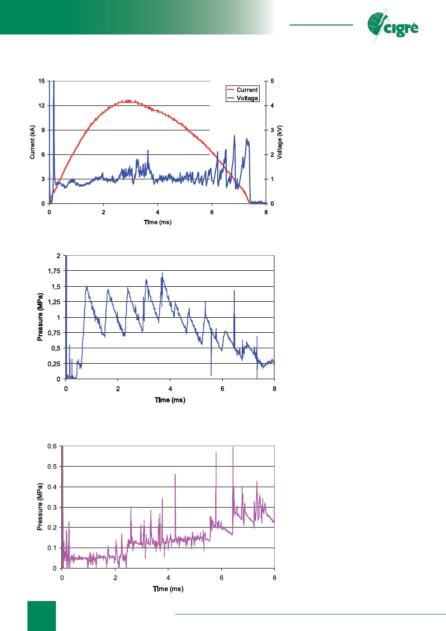
electrodes. Fig. 1 shows oscillograms of current and
voltage in AD. The discharge duration (~ 7,5 ms) is close
to half-wave voltage duration at power frequency. At start
time the voltage oscillogram is on a sharp rise, and then
there is a rapid decline. Hereafter the discharge voltage
was varied in a small range. The estimated high voltage
peak duration (~ 20 ms) is equal to electric explosion time
of copper initiator.
There are some voltage pulsations at current fall time,
which are probably associated with arc movement on
the surface of electrodes. Arc movement rate is about
20 m/sec. Analysis revealed that AD column extends
under action of its magnetic
fi
eld with the result of AD
voltage increase which causes shunt breakup with further
voltage decrease. Figures show that typical electric
fi
eld
value in AD column is 0.1—0.3 kV / sm.
High-speed shooting of the discharge showed that
plasma glow was concentrated close to electrodes at the
beginning. At this point the glow area started to expand at
a rate of 0.3 km/s, however in 0.5 ms the rate decreased
36
August 25–29, France, Paris
Fig. 1. Current and voltage oscillograms (current vs. time)
approximately threefold. Thus, the
plasma expansion rate was much
lower than the speed of sound in
TO, which is about 1.4 km/s [10].
Radiation
fl
ashed over the electrode
spacing in about 1 ms after AD
occurrence.
Fig. 2 and 3 show liquid pressure
"oscillograms" from the same
experiment as current and voltage
oscillograms in Fig. 1. As Fig. 2
and Fig. 3 show that variation of
pressure in TO is repetitively-pulsed.
It could be seen quite distinctly
especially in the beginning of arching
which is about 3 ms. The
fi
rst six
pressure extremums (maximum and
minimum) were registered with PS1
and PS2. The time difference between
them were approximately 0.1 ms.
This time delay was the same as time
difference of sound propagation in
TO from AD burning area to pressure
sensors location. Herewith PS1 signal
was ahead of time from PS2 signal
which is associated with location of
sensors. Correlation from different
pressure sensors started to decrease in
about 3 ms after the AD occurrence.
Apparently, it’s associated with
arc movement on the surface of the
electrodes. AD is moving to body
foot towards PS1 under the action of
ponderomotive force.
Fig. 2 shows that the
fi
rst pressure
extremums followed at 0,8 ms
interval, then one-step transition was
down to
≈
0,6 ms. There is some
correlation between the signals from
pressure sensors and the discharge
voltage oscillogram. Thus, the
fi
rst
PS1 pressure maximum is equivalent
of the "smeared" voltage maximum.
There was a voltage step up to
2.2 kV in 3.64 ms after arc ignition
(Fig. 1) before the absolute pressure
maximum in the oil, which was
fi
xed
in 3.71 ms after AD occurrence and
amounted to
≈
1,7 MPa (Fig. 2).
Apparently, there were sound waves
in a liquid under a sharp voltage
decrease (breakdown).
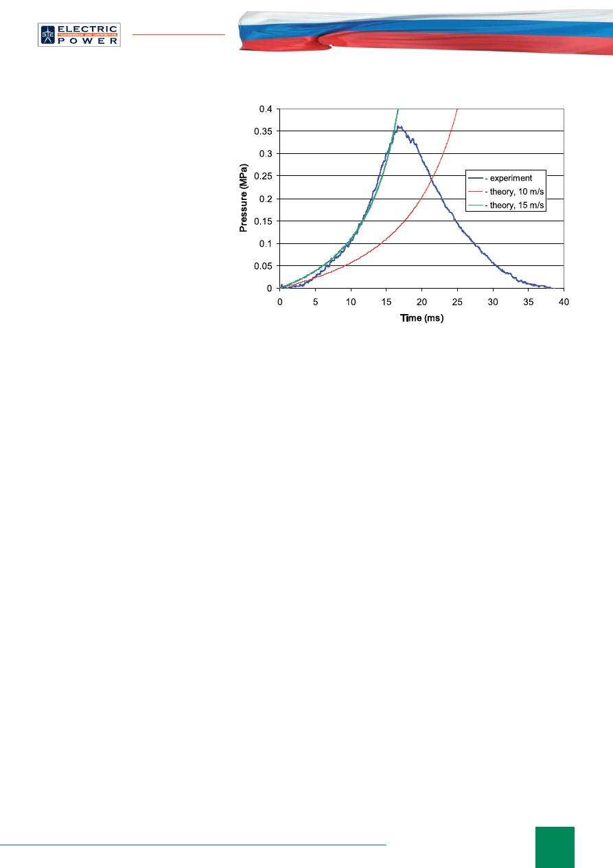
Fig. 4 shows a pressure
oscillogram measured in nitrogen. TO
rises under the in
fl
uence of expanding
gas-vapor bubble, which leads to gas
compression and pressure increase.
Fig. 2. Pressure in TO close to the foot (pressure vs. time)
Fig. 3. Pressure in TO close to “liquid-nitrogen” interface
(pressure vs. time)
Equipment Protection
37
info@eepr.ru, www.eepr.ru
According to high-speed shooting the
liquid level rises uniformly up to 0.1 m
of height, than vapor-gas mixture
ruptured to nitrogen area. Typical liquid
rise rate is approximately 10 m/s, which
is signi
fi
cantly less than the speed of
sound in nitrogen, that’s why the process
of compression is adiabatic. Fig. 4 shows
the calculations of Poisson adiabatic
pressure in gas at two values of liquid
rise rate, which determine gas volume
rate. As
fi
gure shows, the calculated and
measured pressure values are consistent
with each other.
The data of liquid rise rate allows to
calculate components of energy balance
in AD. In the experiment
Q
a
energy
value was 64 kJ and the liquid maximum
kinetic energy was 3.5 kJ. Thus, the
liquid kinetic energy transferred 5—10%
of total energy released in the discharge,
and the main part of the energy was needed for TO heat
and its decomposition.
After discharge in TO the overpressure in nitrogen
“blanket” was at 10—50 KPa level, which is proportional
to gas volume released due to TO decomposition. The
process of gas formation under AD in TO is characterized
by ratio of gas formation
Bg
, which is the ratio of
released gas volume to AD energy. According to our data
Bg
= 0.11 liters / kJ.
According to our tests approximately the same value
of gas formation under AD (0.1—0.11 liters / kJ) was
calculated for insulating
fl
uids from vegetable oils (rape,
soya, castor). The electric
fi
eld in AD column burning in
vegetable oils is 0.1—0.3 kV/cm.
Carried out experiments allow us to de
fi
ne qualitative
features of AD dynamic effect in TO to HV OFEE body,
the main of which is lack of shock waves in liquid. Perhaps
a shock wave occurs at the moment of initiator explosion,
but it quickly degenerates into a sound wave. The average
pressure rise rate in liquid is 0.3—0.5 MPa/ms. At the
background of increasing pressure of body walls there
are intensive sound waves. According to our data the
maximum pressure of body wall in our experiments was
about 2 MPa. The pressure in the arc burning zone was
slightly higher. The rate of “liquid- nitrogen” interface
due to expansion of vapor-gas bubble was 10—20 m/s.
Estimated that pressure in vapor-gas bubble at such
boundary
fl
uid rate should be 5—10 MPa.
ARCLESS SOURCE OF PULSE PRESSURE
(ASPP)
The research results of AD de
fi
ned the requirements
for arcless source of pulse pressure (ASPP) using for
simulating AD effect in HV OFEE. The pressure pulse in
ASPP is generated under the expansion of jet of powder
gases (JPG) produced due to combustion of explosive
Fig. 4. Overpressure in nitrogen (pressure vs. time)
materials (EM). It is important that duration of pulse
pressure effect should be about 50 ms. This fact excludes
the possibility of EM using for JPG with the necessary
parameters such as hexogen or trotyl. Therefore, in our
experiments we used gunpowder as EM, because it burns
much slower than trotyl. Gunpowder ef
fi
ciency is 3.8
kJ/g, speci
fi
c gas production — 0.9 l/g.
SPG generator was a high-pressure body, where EM
combustion products
fl
ew out from Laval nozzle. The
pressure pulse magnitude and duration can be controlled
by changing nozzle area, EM mass, EM allocation in
combustion body and ignition methods. Experiments
were carried out in the same body as AD experiments.
JPG generator was attached to one of the lower windows,
so that the area of JPG in
fl
uence was the same as under
arching. TO and water were used as working
fl
uids. Heat
rate under EM combustion
Q
was varied in the range of
10—50 kJ.
Pressure was measured at characteristic points of the
body, high-speed shooting of the liquid was recorded
under JPG in
fl
uence. According to measurements jet
pressure at the entrance of the liquid was about 10—
20 MPa for approximately 1 ms. Duration of jet exposure
to the liquid was varied from 20 to 60 ms. A typical
pressure value of body walls was about 1 MPa. Motion
state of "liquid-nitrogen" interface under SPG in
fl
uence
immersed in the liquid was the same as under AD under
the same energy effect. The interface, while remaining
fl
at, was rising at a rate of 10—20 m/s. It should be noted
that there were no big differences between water and
transformer oil response for JPG impact.
The experiments proved the possibility of hydraulic
similarity of liquid
fl
ow under the JPG and AD effect. The
equivalence of the liquid under JPG and AD effect was
achieved by energy equations and duration of exposure.
In this context, JPG generator (ASPP) can be used in
38
August 25–29, France, Paris
explosion protection tests for simulating AD effect in HV
OFEE body.
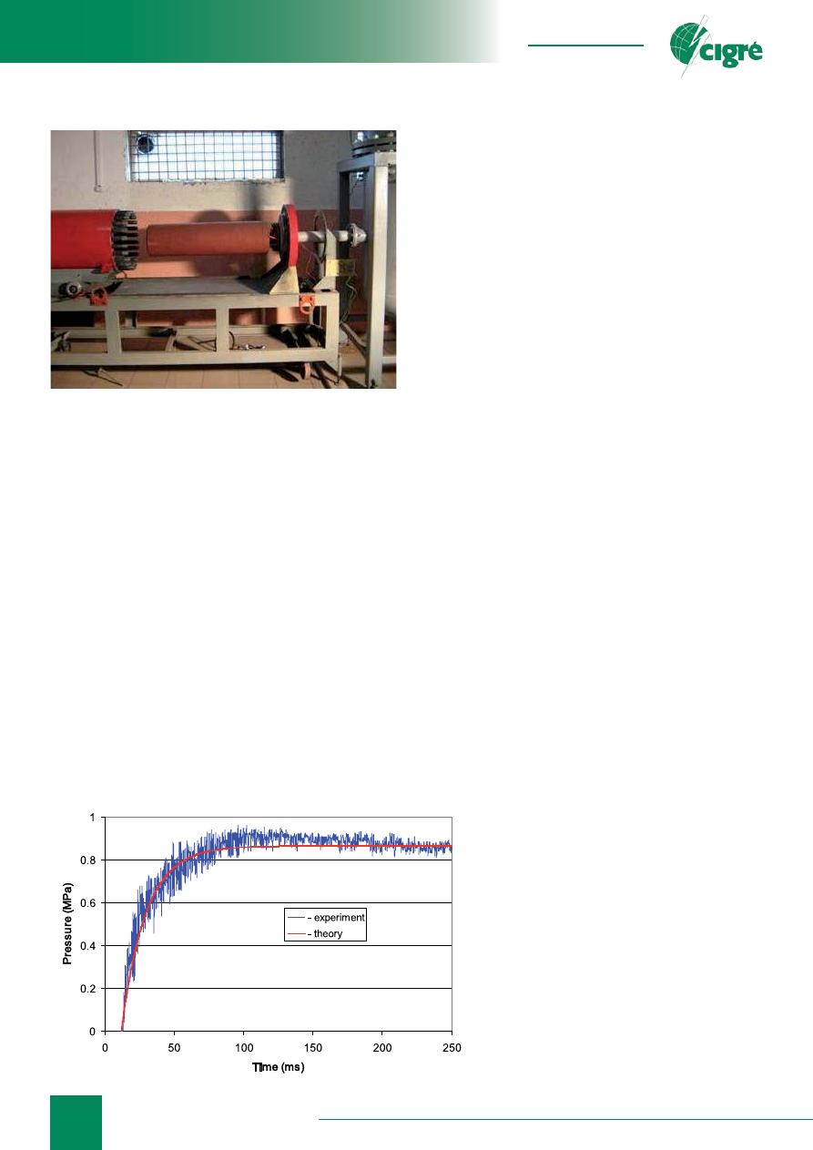
Fig. 5 presents ASPP calculated for energy of 5 MJ
before the test of "shooting" from ASPP to controlled
container
fi
lled with air. Fig. 6 shows an "oscillogram"
of pressure in the controlled container. This
fi
gure also
shows the calculated pressure values. As it seen, the
experiment is coherent with the calculation. After reaching
the maximum measured pressure value is reduced due
to powder gases cooling. In the model this effect was
not taken into account. This fact explains the difference
between theory and practice over the time.
ASPP can be used for series of tasks aimed to improve
the explosion protection of HV OFEE:
• Test of HV OFEE production samples;
• Examination of explosion protection systems and
devices ef
fi
ciency;
• Elaboration of HV OFEE new constructions with high
level of explosion protection, model testing;
• Basic data acquisition for development and veri
fi
cation
of numerical methods for HV OFEE perspective
constructions and explosion protection systems.
EXPLOSION PREVENTION TESTS FOR
INSTRUMENT TRANSFORMERS
The explosion protection tests using ASPP were carried
out with serial current transformers (CT) and voltage
transformers (EVT). Test results were described in detail
in studies [9, 11, 12]. A brief summary is presented here.
Transformer models, characteristic values of internal short-
circuit currents and the expected AD energy maximum
are shown in Table 1. The calculations of AD energy
maximum were based on fault currents and transformer
design data from manufacturing plants. During the tests,
pressure sensors were installed at different distances from
JPG input inside the transformer. This test was recorded
by high-speed shooting from two mutually perpendicular
directions with a time resolution of less than 3.3 ms.
Area of SPG effect was consistent with most probable
occurrence of AD area. Transformers were
fi
lled with
transformer oil of GC brand during the tests.
The design of tested transformers was considerably
different. In CT manufactured by Russian Federation
the tank with windings are installed in the bottom
where located the porcelain insulator with the pressure
compensator in bellows form (Fig. 4). Bellows provides
compensation of oil volume temperature changes and
protection of internal insulation from humidifying. In
instrument transformers manufactured by Ukraine the
tank with windings are installed in the top. Protective
bellows are located under the tank with windings. CT 330
is equipped with protective membrane instead of bellows.
110 kV CT
According to test results, exposure time at transformer
overpressure of 0.5 MPa was approximately 60 ms. By
means of high-speed shooting was de
fi
ned
that basic deformation of the body has
occurred during the
fi
rst 20—25 ms after
ASPP ignition, when overpressure inside
CT was about 1 MPa. The transformer
body has undergone considerable plastic
deformations, thus its volume has increased
approximately up to 8.5 liters (12%).
Deformation of the body did not caused
TO leakage.
110 kV Voltage transformer (EVT)
Exposure time of ASPP at energy of
1MJ was 60—70 ms. EVT overpressure
was at 0.5 MPa. In 10—15 ms after ASPP
start the
fl
ange of protective membrane
began to move and
fi
nally torn off. The
bellows has started to move approximately
in 15 ms after ASPP start and it was
completely opened approximately in 20 ms.
Fig. 5. ASPP calculated for 5 MJ
Fig. 6. Pressure in controlled container versus time response
characteristics (pressure vs. time)
Equipment Protection
39
info@eepr.ru, www.eepr.ru
№
Transformer
model
Producer,
factory
Fault
current
range, k
А
Energy
Q
a
, MJ
Exposure
time of
ASPP, ms
1
110 kV CT
Russian
Federa-
tion
1.5—3
0.4 60
2
330 kV CT Ukraine
5—10
1
60
3 110 kV EVT Ukraine
15—20
1
70
Table 1. Instrument transformers tested by ASPP
The internal pressure maximum was about 4 MPa,
pressure growth rate was about 1 MPa/ms. The protective
membrane was torn off and TO stream level was risen up
to 10 meters. Thus radius of TO disorder was less then
radius of standard safety zone. There were no visible
deformation of transformer metalware and baseinsulator
as opposed to bellows and top guard vessel.
330 kV CT
Tests of two CT models has been carried out. Essential
design defect of the high-voltage block of the tested
model have been revealed during
fi
rst test. The jet of
TO with velocity of 20 m/s started to
fl
ow from service
openings located in this part of CT after ASPP start.
Jet range was about 40 meters. This design of CT has
been rejected. Further results of tests using modernized
design of the high-voltage block are considered. Service
openings in new block have been eliminated, and bellows
instead of a protective membrane has been established.
The considerable plastic deformations of body after tests
have been observed. The maximum deformation of the
transformer body was up to 30 mm, a de
fl
ection of top
fl
ange edges was 20 mm and a swelling of the transformer
top cover was 40 mm. Insulation of transformer windings
has been considerably broken down.
According to accepted de
fi
nition these three tested
transformers including modi
fi
ed CT of TFRM type can be
recognized as explosion-proof and
fi
reproof at AD energy
values from Table 1.
SPECIAL ASPECTS OF TRANSFORMER
EXPLOSION
According to analysis of published studies, the most
vulnerable elements of internal faults occurrence in
power transformers are bushings, oil-
fi
lled cable box and
tap changers. AD develops close to the point of a short
circuit origin between transformer body ("the ground")
and construction elements under high potential. The
length of arc column de
fi
ning AD voltage depends on HV
OFEE construction may range from 0.1 to 0.3 meters.
AD continuously and randomly transfers along internal
surfaces of the transformer due to ponderomotive forces
and convective currents. Since the AD characteristic
average rate is about 10 m/s and the time of its
“lifetime” — ~ 50 ms, the surface area of the transformer
under AD effect is ~ 0,1 m
2
. Therefore, AD transfers inside
the volume of 10-30 liters. This fact gives a reason for
shock wave absence in HV OFEE despite the high power
of AD.
Pressure equalization period inside transformer tank
is estimated as sound wave double transmission time
of maximum distance between opposite walls of the
transformer. Pressure equalization period in 330 kV
instrument transformers which are similar to previously
discussed transformers is ~ 1 ms. This period is less than
arc duration. Pressure equalization period in distribution
transformers is ~ 15 ms. This means that there is a high
pressure differential in large transformers during arching.
The maximum value is achieved in arching zone. These
calculations show that small transformers should be
destroyed uniformly across the surface under the pulse
pressure in
fl
uence. Such damages were recorded during
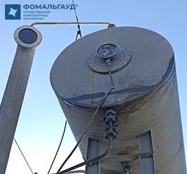
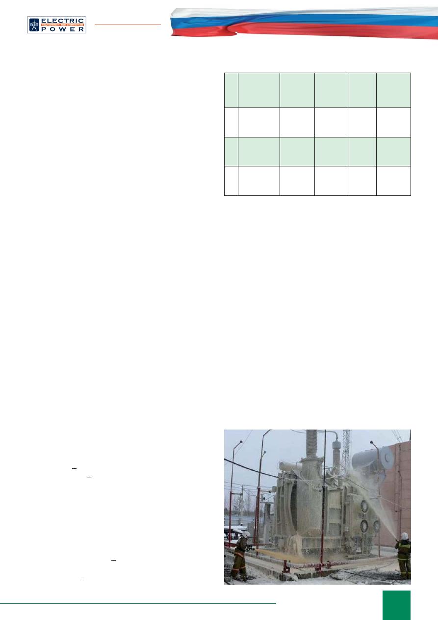
our tests of instrument transformers. Failure mode of large
transformers is local where the damaged area is less than
10% of total surface area. An example of such damage
is shown in Fig. 7 — Transformer in Western Siberia
Substation.
The maximum overpressure for transformer body
depends on design, location and pulse duration.
According to general requirements for transformer
body deformation should be in elastic zone with static
overpressure of 0.05 MPa. There is tank rupture under
dynamic loading of the transformer at overpressure
above 0.5 MPa for more than 5 ms.
Apparently most probable conditions for transformer
explosion are in the range of 10—30 ms after AD ignition.
At early stage of AD burning for about 10 ms, internal
pressure of the transformer does not reach critical values.
Fig. 7. Transformer in Substation after explosion

40
August 25–29, France, Paris
At later stages of AD in about 30 ms, the probability
of explosion is lower. Firstly, AD electric power is
signi
fi
cantly reduced due to increase of insulating
fl
uid conductivity. As a result there is a decrease of gas
formation rate in AD and changes in pressure growth
rate. Secondly, there is an effect of internal volume of the
transformer tank due to elastic and plastic deformation
of the walls under high pressure in
fl
uence by this point
of time. The additional volume partially compensate for
pressure growth due to TO decomposition.
In the view of foregoing considerations, we can lay
down basic requirements for explosion protection systems
of HV OFEE:
• the response time for internal pressure increase should
not exceed 5 ms;
• the system should limit the pressure maximum in the
transformer tank at the level of 0.3—0.5 MPa.
Protection system should be installed close to problem
areas of the transformer in case it is not possible to protect
the entire internal surface.
MODEL TESTS FOR EXPLOSION
PROTECTION OF HV OFEE
Well-known protection methods of HV OFEE focus
on formation of additional volume
Δ
V for expansion of
TO in case of internal pressure growth under AD. The
effectiveness of the protection system can be estimated
from:
k
=
Δ
V/ B
g
Q
a
(1)
The
k
value so-called a protection system reliability
parameter is the ratio of the additional volume of TO and
gas volume released due to TO decomposition under AD.
Approximately we can take as follows
•
k
> 0.7—0.8 tank deformation is elastic and the
equipment is explosion safe as well as explosion proof;
• 0.3 <
k
<0.7 should be considerable plastic deformation
of the transformer body;
•
k
< 0.1—0.3 should be expected explosive destruction
of the body.
Tentatively we can take typical values of protection
system reliability as
k
1
~ 0.7—0.8
и
k
2
~ 0.1—0.3.
There are two ways of additional volume formation
for TO in literature. The
fi
rst method is based on
using porous coverings on the internal surfaces of HV
OFEE body [13]. It is expected that porous material
is compressed under high pressure in
fl
uence resulting
formation of available volume, which is
fi
lled with
expanding hydrogen, carbon oxides and hydrocarbon
gases due to decomposition of TO. In consequence
pressure growth inside the body is limited. Additional
protective effect can be achieved in case compression
of material is enough to spend a signi
fi
cant portion of
kinetic energy of TO
fl
ow for compression. "Porous
covering" method may be effective in case substantial
compression of porous material takes place at a relatively
low overpressure — approx. 0.3—0.5 MPa. Up to the
present day this method of protection has not passed the
tests and it’s not used in practice.
The second method of protection is so-called "protective
membrane" method. Principle of method is installation
of protective membranes on HV OFEE body which are
destroyed under action of AD pulse pressure and used for
TO
fl
ow to special container. [14] It is considered that this
way internal pressure of HV OFEE can be kept within
acceptable limits. The second protection method is widely
used, for example in SERGI Transformer Protector system.
Porous covering method
In the experiments of this protection method we used
HV OFEE breadboard model which looks like steel
cylindrical tank of 0.95 m
3
volume and 1.45 m height
with a conical nozzle at the bottom. Tank diameter was
1 m, thickness was 7 mm. The cover has been screwed
to a sidewall by 24 bolts with thread diameter of 12 mm.
The plate of polyfoam of 50 mm thickness has been glued
on a steel cover of a breadboard model. The polyfoam
was made from extruded crumb with 0.04 kg/dm
3
density.
The tank was
fi
lled with water. ASPP was installed at a
distance of 0.2 m from the top cover. Estimated value of
ASPP pulse was 0.35 MJ.
Figure 8 shows a shot with breadboard model in 80 ms
after ASPP start, when the cover has lifted in 0.8 meters.
After experiment only 3 bolts from 24 has survived, the
cover de
fl
ection has amounted to 50 mm, the polyfoam
has crumbled into small fractions.
Hence the discussed protection method of porous elastic
covering cannot protect OFEE body from considerable
deformation under action of a high pressure pulse. This
result was expected. Indeed for the effectiveness of this
protection system needed volume increase which is
accessible for the liquid due to compression of porous
material for its compensation in 3—5 ms — the time of
pressure rise in the liquid. This is possible either at slow
pressure rise rate of 0.1 MPa/ms, or at small sizes of the
Fig. 8. Test of HV OFEE breadboard model with
porous covering
Equipment Protection
41
info@eepr.ru, www.eepr.ru
protected model of 0.1 meter. The
main impulse load took only a part
of tank working surface under AD
and internal volume increased due to
compression of porous material was
not enough to prevent an explosion.
These tests were carried out using
polyfoam as a damper material.
It’s possible to use other damper
materials with different properties.
However, the ef
fi
ciency of the
protection system in general cannot
be suf
fi
ciently high. This fact can be
illustrated by following calculations.
If the typical size of transformer tank
is
a
, then the possible increase of
available oil volume under covering
of transformer internal surface
with damper material of maximum
compression
h
will be about:
Δ
V
~
6a
2
h
(2)
The porous covering regularly
compresses under action of pulse
pressure only in case tank size is under
~ 0,5 m. Taking for calculations that
a
~ 0,5 m and
h
~ 0,02 m, we
fi
nd by
formula (2),
Δ
V
~ 30 liters. It may be
enough to protect the transformer from the explosion at
AD energy of 0.5 MJ (
Vg
~ 55 liters).
At the increasing size of transformer tank after
short circuit occurrence the covering can be effectively
compressed only close to the short-circuit origin with total
area of 1 m
2
. In this case, the additional volume will be
Δ
V
~ 20 liters. The effectiveness of this protection system
under AD energy
Q
a
~ 1 MJ (
Vg
~ 110 liters) will be
k
~ 0.2, i.e. even at a relatively low AD energy we can
expect explosive destruction of tank.
In summary, porous coverings which are compressed
at pulse pressure of 0.3—0.5 MPa, having an effective
Young's modulus of 0.5 MPa, may be used in explosion
proof transformers with the tank size up to 0.5 meters if
expected AD energy does not exceed 0.5 MJ. In addition
this porous covering material has to maintain its properties
during continuous operation.
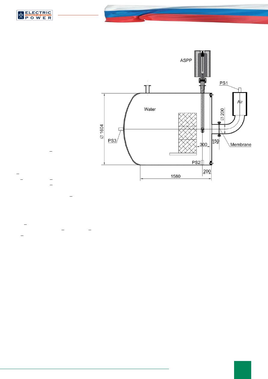
Method of a protective membrane
Fig. 9 shows a test of OFEE breadboard model using
this protection method. The HV OFEE model looks like
steel cylindrical vessel of 1,4 m diameter
fi
lled with water.
The thickness of breadboard model steel cover is 12 mm.
The air volume has been separated from the water by an
aluminum membrane with the thickness of 0.2 mm and
diameter of 200 mm. The concrete blocks of 70 kg have
been installed at a distance of 300 mm from the cover to
simulate transformer windings. Area of ASPP effect was
between concrete blocks and cover at 0,2 m distance from
roof opening — opposite the PS2. PS1 detected pressure
in air bubble behind the membrane, PS3 and PS4 detected
pressure in
fl
uid from far
fi
eld of ASPP effect. The pulse
action for HV OFEE body was recorded by high-speed
shooting. Pulse energy of high pressure was 1MJ, pulse
duration was 50 ms.
Membrane contact sensor recorded its rupture in 3 ms
after ASPP start. The water
fl
ow rate through membrane
calculated due to air pressure changes in air bubble
behind the membrane was 20 m/s. Pressure maximum in
the liquid has reached 1.8 MPa. High-speed shooting has
shown that the deformation of HV OFEE body had lasted
for 10—15 ms. After the test we found out that the residual
deformation of steel cover was about 40 mm and concrete
blocks were moved for 50 mm. The conditions for the
discussed protection method in this test were optimal: a
thin membrane of a large diameter was installed right in
front of the epicenter of the pressure rise. However the
present protection method was not effective enough.
The tank rupture prevention system in Fig. 9 is a
simpli
fi
ed version of SERGI Transformer Protector (TP)
system. This protection system is used in energy utilities of
Russia in recent years, but the experience of its operation
is not encouraging. On September 22, 2009 there was an
explosion of AT-1 — 330 kV tank due to ISC at substation
"Mashuk", where this system was installed. SERGI gave
an explanation of this rupture in the report [15]. According
to this report there was a peak current of 10 kA and arc
duration of 60 ms at the time of rupture. In the analysis
of TP system SERGI experts assumed the AD voltage
of 37 kV, so that the energy released in AD was about
Fig. 9. HV OFEE breadboard model for tests using protective
membrane method
42
August 25–29, France, Paris
11 MJ. This AD voltage value seems conservative, because
it was calculated without taking into account the voltage
loss in inductance. According to our estimates, the AD
voltage was signi
fi
cantly low, so that the total AD energy
was about 4 MJ. GPFD volume (gaseous products of
fl
uid
decomposition) was about 0,45
м
3
under this
Q
a
energy.
According to data [15] the protective membrane of
8 inches diameter (~ 250 mm) was destroyed in 4,5 ms
after short-circuit occurrence at pressure of 0.08 MPa.
There was TO
fl
ushing through the opening which
caused "Depressurisation" of transformer tank in 112 ms.
According to this report [12], even though the TP system
did not protect the HV OFEE body from explosion it
prevented the
fi
re occurrence. However, the data in the
report [15] raise some doubts. According to this data the
maximum oil
fl
ow rate through the destroyed membrane
does not exceed 20 m/s. According to calculations based
on report values of TO
fl
ow rates, approximately 25 liters
of TO were leaked through the diaphragm under AD.
Therefore, the reliability coef
fi
cient of the protection
system (1) is
k
~ 0.07, that’s why TP couldn’t protect HV
OFEE tank from explosion. As for the lack of
fi
re, the
probability of its occurrence after rupture does not exceed
20%, so we cannot give a credit to TP system especially as
Q
a
energy was relatively small.
For information, the autotransformer tank rupture after
explosion on "Mashuk" substation was local, total damage
area was 1
м
2
.
TESTS OF DYNAMIC PROTECTION
SYSTEM
The analysis shows that well-known explosion
prevention systems of HV OFEE are not effective enough
and it’s a necessary to develop new protection systems.
This section brie
fl
y describes tests results of dynamic
protection system (DPS) developed in Joint Institute
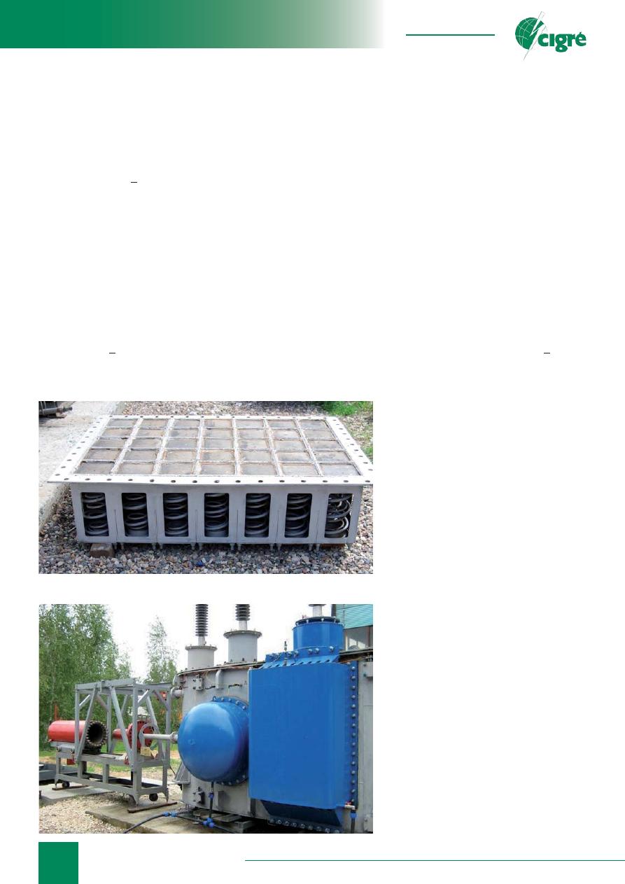
for High Temperatures, Russian Academy of Sciences.
The main elements of DPS are spring-loaded running
blocks (Fig. 10). The blocks were installed on the side of
transformer body close to the most probable occurrence
of short circuit area. The maximum displacement of the
blocks under in
fl
uence of pulse pressure was ~ 0,3 m.
Protection of bushings was carried out
using special diaphragms.
The tests were carried out in
autotransformer (AT). The autotransformer
was out of service, but all the elements
have been preserved inside the body. Fig.
11 shows a photo of the transformer with
established DPS elements (guard vessels are
painted blue). There were 16 running blocks
under circular guard vessel and 35 blocks
under rectangular guard vessel (Fig. 10).
There was an ASPP inside the protective
chamber from the left. DPS wasn’t installed
at the back side of the transformer, it was
installed at one of three bushings.
ASPP with energy of 1 to 3 MJ and
exposure duration of 30 to 50 ms was
used in the tests. High-speed shooting
(up to 2000 frames per second), four PS
and displacement sensors were used for
diagnostics of the tank deformation. The AT
tank was
fi
lled with water.
A series of experiments were carried
out. The pressure pulse was supplied to
most likely points of short circuit origin
from both sides of transformer, including
the bushing area. Plastic deformation of
the tank with partial destruction of the
structural elements but without leaks was
recorded under pulsing of the back side of
autotransformer without DPS. High-speed
shooting has recorded that blocks started to
move in 5 ms after pulsing.
The study highlights:
• pressure maximum in autotransformer
breadboard model increases approximately
Fig. 10. Dynamic protection system (working valve
block without guard vessel)
Fig. 11. AT with DPS before tests
Equipment Protection

43
info@eepr.ru, www.eepr.ru
in proportion to ASPP energy: under the energy of 1 MJ
pressure maximum is about 0.5 MPa, under the energy of
3 MJ the pressure exceeds 1 MPa.
• The basic body deformation without DPS starts in
20—30 ms after the pulsing.
• Displacement rate of blocks with DPS increases due
to ASPP energy increase: maximum velocity of blocks
reaches 30 m/s at ASPP energy of 3 MJ.
• DPS has much lower response time in comparison with
the factory explosion protection system of protective
membrane.
• DPS installed in front of the pulse pressure bushings
protects the body from plastic deformation up to 3 MJ
of pulse energy.
It is estimated that DPS with tested con
fi
guration has
reliability coef
fi
cient
k
~ 0,5. The reliability of explosion
protection can be increased from 30 up to 50% in case
DPS is installed both on sides of the transformer and all
high-voltage bushings.
CONCLUSIONS
1. Presented research results of transformer oil
fl
ow
and liquid
fl
ow under action of AD and jet of powder
gases (JPG). The study shows that the transformer oil
fl
ow and liquid
fl
ow under action of AD and JPG impact
are similar at equal values of energy duration and energy
exposure.
2. Developed an arcless source of pulse pressure
(ASPP) for
fi
re and explosion prevention tests of HV
OFEE under energy of 5 MJ.
3. Developed test method for HV OFEE using ASPP.
The proposed method is recommended for model tests
and for evaluation of explosion prevention system
performance for all types of HV OFEE. This method is
used as an alternative to existing method based on AD
initiation inside the equipment.
4. Described experience of explosion tests for serial
instrument transformers.
5. Experimentally shown that the protection method
of porous coverings which can be compressed under
high pressure of expanding vapor-gas bubble on internal
surfaces of HV OFEE cases — cannot be effective for
large transformers.
6. Test models of “protective membrane” method
showed that this method didn’t protect HV OFEE body
from plastic deformation to its explosion. Reliability
parameter of this protection method doesn’t’t exceed 0.1.
7. Presented dynamic protection system (DPS) of
explosion prevention for HV OFEE. Tests of DPS installed
inside autotransformer showed that DPS prevents the
explosive destruction of the autotransformer body at least
at the energy of 3 MJ.
LITERATURE
1. Darian L.A., Arakelian V.G, Gas-resistance of
insulation liquids. Electrotechnika (rus)
№
2, 1997, p.
45—49.
2. Vanin B.V., Lvov U.N., Neklepaev U.N. etc, About
faults of 110—500 kV transformers in service // Power
stations. 2001.
№
9. p.53.
3. Petersen A.,«The Risk of transformer
fi
res and
strategies which can be applied to reduce the risk» //
Session CIGRE-2010. France. Paris. 2010. Report A2-
101.
4. Foata M., Dastous J.B.,«Power transformer tank
rupture prevention // Session CIGRE-2010. Paris.
2010. Report A2-102.
5. Darian L.A., Dementiev Yu.A., Efremov V.P.,
Polistchook V.P., Shurupov A.V., Alternative method
of estimation of explosive safety of high-voltage oil-
fi
lled electrical equipment, Electro, N 5, P. 43—46,
2009.
6. Daryan L.A., Kozlov A.V., Luzganov S.N., Povareshkin
M.N., Polistchook V.P., Shurupov A.V., Shurupova N.P.
Experimental study of a
fl
ow of liquid under action of
an arc discharge and jet of powder gases// Physics of
Extreme States of Matter- 2010. Chernogolovka. 2010.
P. 112.
7. Daryan L.A., Kozlov A.V., Kotov A.V., Povareshkin
M.N., Polistchook V.P., Shurupov A.V., Shurupova
N.P., Pulse arc discharge in mineral and organic oils//
Proceedings of Int. Conf. on Physics of Extreme States
of Matter-2012. 1—6 March, Russia, Elbrus. Institute
of Problems of Chemical Physics. Chernogolovka.
2012. P. 168.
8. Darian L.A., Kozlov A.V., Luzganov S.N., Povareshkin
M.N., Polishuk V.P., Shurupov A.V. Shurupova N.P.,
Pulsed arc discharge in mineral and organic oils //
Proceedings of Low Temperature Plasma Physics —
2011. Petrozavodsk. 2011. Publisher Petrozavodsk
State Universitety. Vol. 1, p. 106—111
9. Darian L.A., Kozlov A.V., Povareshkin M.N., Polishuk
V.P., Shurupov A.V., Son E.E., Fortov V.E., Arcless Tests
of the High Voltage Oil-
fi
lled Electrical Equipment on
Explosion-proof // News of RAS. Energetics. 2011.
№
5.
p. 74.
10. Physical quantities. Catalogue edited by Grigorieva I.S.
and Melikhova M.: Energoatomizdat. 1991. 1260 p.
11. Darian L.A., Polishuk V.P., Shurupov A.V., Arcless Tests
of the High Voltage Oil-
fi
lled Electrical Equipment on
Explosion-proof. Energo-info (rus), 2012,
№
9, p.54—
58.
12. Darian L.A., Kozlov A.V., Povareshkin M.N., Polishuk
V.P., Shurupov A.V., Arcless Tests of the High Voltage
Oil-
fi
lled Electrical Equipment on Explosion-proof //
Electro. 2011.
№
5. p. 23.
13. Mishuev A.V., Kazennov V.V., Gromov N.V., Fire and
explosion protection device for transformer under AD.
Patent RU 2334332.
14. Manie F., Explosion protection device for transformers.
Patent RU 2263989.
15.
SERGI company. Substation «Mashuk». Activation
of Transformer Protector on 22/09/ 2009. Reference
Are61rr00.03e
от
09/10/09.
Оригинал статьи: Tеst Models for Explosion Protection of High Voltage Oil Filled Electrical Equipment
Life time of transformers or another HV oil-fi lled electrical equipment (HV OFEE) is about several decades. The gradual degradation of paper-oil insulation occurs under the infl uence of partial discharge, heating, cavitation and other factors in service.