
The MAIN JOURNAL for POWER GRID SPECIALISTS in RUSSIA
44
r
e
l
a
y
p
r
o
t
e
c
t
io
n
rela
y prot
ection
Synchronous Сlosing
During High-speed
Transfer System Operation
O
ne of the requirements to
high-speed transfer systems
is busbar coupler (BC) clos-
ing when voltage vector on
the intact busbar section and EMF vec-
tor of the generalized motor running
down to the busbar section with power
failure have a small phase difference
(a range is up to 30° in [1]).
This requirement is valid since it al-
lows to minimize transient current when
the busbar coupler is closed. However,
non-zero time of BC closing (
T
ON
), ignor-
ing the rate of frequency change and
methodical errors when determining
angle and frequency in digital blocks can
lead to a violation of this requirement.
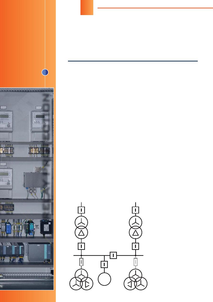
Let’s consider the power loss mode
on busbar section no.1 (BS1) to which
the synchronous motor (SM) is connect-
ed. It is assumed that voltage magnitude
and frequency are constant on the intact
busbar section no. 2 (BS2) (Figure 1).
The equation of motion for the vol-
tage vector of busbar section 2 (BS2) is:
BS2
=
r
·
t
+
0 BS2
where
BS2
– current phase, rad;
r
– ra-
ted circular frequency (rotating speed),
rad/s;
0 BS2
– initial phase, rad.
The motion law for BS 1 voltage
vector depends on the law of motor
rundown (see below). During power
failure, the voltage on BS 1 is induced
only by motor excitation
fi
eld. In this
case, voltage frequency and phase are
clearly associated with rotor spinning
frequency and phase. In general, the
motor rundown law is Newton's second
law for spinning bodies:
d
2
J
— =
M
(1)
d
t
2
where
J
is inertia moment of rotating
mass, kg·m
2
;
– rotor rotation angle
relative to the preselected
fi
xed axis,
rad;
M
– total moment of forces acting
on the body, N·m.
When the equation (1) is integrated
two times in the course of
fi
nding the
(
t
) dependence, two constants pre-
sent themselves, which are determined
by the initial conditions:
0
– initial angle
(the angle at the initial moment of time),
rad; (
d
/
d
t
)
t
= 0
=
0
–
initial rotating speed,
rad/s.
In order to give the
BC closing command, it
is necessary to predict
the angle at the time of
breaker closing. For this
prediction, it is essential
to know the angle be-
tween voltages (
i
), the
rotating speed (
i
) and
the formula for
M
-func-
tion (dependence/inde-
pendence of the total
BB1
СB
Q
SM
VT BS 1
VT BS 2
BB2
Figure 1.
ВВ
– air blast breaker;
СВ
– bus section breaker;
SM – synchronous motor;
VT BS – VT of bus section

45
47th CIGRE Session
Special issue, August 2018
moment on other variables) at the moment of calculation
(
i
-th moment of time).
Let’s analyze each of those parameters and estimate
the closing angle error related to the inaccurate determi-
nation of the parameters.
FREQUENCY
Frequency calculation in protection relays is a non-trivial
task and can be carried out in various ways [2, 3]. We
assume here that the algorithm calculates frequency
without error, but has an averaging window to improve
result reliability (for example, the standard [4] requires
frequency calculation for no longer than 60 ms).
As a result, when frequency varies linearly and fre-
quency values are averaged over the time
T
AV
, the algo-
rithm gives an error equal to:
f
= –
f·
T
AV
/
2 (2)
where
f·
– rate of frequency change, Hz/s;
T
AV
– averag-
ing time, s.
According to the equation (2) above, in case of fre-
quency increase, the measured frequency will be under-
valued, and vice versa.
When estimating the angle of voltage vector rota-
tion during breaker closing time, the frequency error (2)
gives an error in the angle equal to:
1
= 2
·
f
·
T
ON
. (3)
Moreover, the real vector will describe an arc larger
than the calculated one.
ANGLE
In order to analyze angle error, let us consider one of
the most common methods of transition from sample
values to vectors. This is separation of the main har-
monic by means of the Fourier series expansion:
t
C
=
jy
·
e
–
j
t
d
t
.
t
–
T
If input signal frequency differs from the frequency
used to calculate the orthogonal components (and we
have already identi
fi
ed it is so, even if frequency adjust-
ment is taking place in the protection relay), then the
function under the integral is:
y
=
A
·
sin
[(
+
)
t
+
]. (4)
The Fourier calculation is performed for one period
of the signal, therefore, linear frequency decrease is not
taken into account in the formula (4).
We can expect that the vector will no longer be un-
moved, but will rotate with a difference frequency
.
Subsequent to integration we obtain:
1
1
C
=
A
·
sin
· —
e
j
(
t +
–
)
– —
e
–
j
((2
+
)
t
+
–
))
2
+
where
=
/
.
The assumption turned out to be true. The vector ac-
tually has a low-frequency component
. However, in
accordance with the amplitude-frequency response of
discrete Fourier transformation, vector amplitude was
changed (by
sin
/
times) and high-frequency compo-
nent 2
+
was added. The end of the vector de-
scribes a hypocycloid.
It should be pointed that the vector on average al-
ways lags behind the "real" vector by an angle
:
2
=
/
. (5)
Thus, when forecasting, the actual vector is already
slightly "further" than protection relay calculates.
MOTOR RUNDOWN LAW
Motor rundown is described by the equation [5, 6, 7]:
d
ˆ
k
LF
— = – — [
m'
0
+ (1 –
m'
0
) ·
ˆ
] (6)
d
t
j
where
k
LF
– motor load factor for active power;
j
– inertia
constant of motor driving unit system, s;
m'
0
– reduced
initial negative torque,
M
0
/(
k
LF
·
M
rt
);
ˆ
– reduced rotating
speed,
/
rt
.
The pace of motor rundown is determined by the ini-
tial acceleration (
d
ˆ
/
d
t
)
t
= 0
= –
k
LF
/
j
=
ˆ
0
.
It is also evident that regardless of motor type (
),
rundown occurs identically at the initial moment of time
and is determined only by load factor
k
LF
and inertia con-
stant
j
.
It is not necessary to numerically solve the equa-
tion (6) in the protection relay, because under real initial
accelerations from 40 to 400 rad/s
2
[5], the deviation of
the rotating speed (frequency) variation law from the li-
near one is small during the time of calculating and ave-
raging performed by protection relays.
However, for the purpose of synchronization, the
angle prediction can be ful
fi
lled based on the assump-
tion that frequency is constant during the time of circuit
breaker closing. In this case, the angle error is equal to:
3
=
·
T
2
ON
/
2 (7)
where
– angular acceleration (frequency derivative),
rad/s
2
.
All errors have the same sign and may
cause a condition under which the actual
voltage vector phase differs more from the
voltage phase of the intact busbar section at
the moment of BC closing than it is allowed
as per the calculations.
Figure 2 shows the angular errors, de-
pending on the initial acceleration when us-
ing ISM15_Shell_FT2 high-speed circuit
0
50
100
150
200
250
300
0
5
10
15
20
25
Initial acceleration
ε
0
, rad/s
2
Angular error
Δϕ
, deg
Dependence on the frequency error
Dependence on the angle error
Dependence on ignoring the linear frequency change
Total error
T
ON
= 22 ms
Figure 2. Dependence of angular errors on the
initial acceleration.
T
ON
= 22 ms

46
RELAY PROTECTION
breaker with CM_1501_01 electronic control module (4) and
with closing time of 22 ms [8]. Figure 3 represents the same
functional relation when using a slow circuit breaker with
closing time of 50 ms (closing time of modern circuit break-
ers may be up to 100 ms).
The inertia constant for gas compressor units with STD-
4000-2 (three-phase synchronous motors) and 280-12-7
supercharger is 3.25 s [9]. Through the inertia constant,
it is possible to calculate the initial acceleration with mo-
tor rundown being 96.6 rad/s
2
. The graphs show that the
methodical error only will be 7 and 18 degrees respectively.
Taking into account the protection relay cyclical calculation,
the angular error will further increase because the "correct"
time for issuing the command may come in the middle of the
program cycle. For high initial acceleration values and CBs
closing within 70-100 ms, the methodical error will be tens
of degrees.
In the BMRZ-BAVR high-speed transfer system pro-
duced by LLC "NTC Mekhanotronika" the following solu-
tions are used for exact determination of the moment of is-
suing the BC closing command:
1. The device analyzes not only the speed but also the ac-
celeration of busbar section vectors rotation relative to
each other.
2. The linear frequency change during breaker closing is
taken into account, because without considering this fact
the error depends on the time of breaker closing qua-
dratically.
3. Adaptive change of
fi
lter order is used for faster re-
sponse to network mode change. The maximum value
of the observation window is half the period. It makes
possible to ignore angular errors when calculating the
orthogonal components.
4. It is preferable to use high-speed circuit breakers, as the
accuracy of prediction decreases for longer periods of
time.
Р
Figure 3. Dependence of angu-
lar errors on the initial accelera-
tion.
T
ON
= 50 ms
REFERENCES
1. OTT-29.130.00-KTN-119-17. General technical re-
quirements. Fast automatic transfer switch devices on
the basis of vacuum circuit breaker with rated voltage
above 1000 V. Moscow, PJSC "Transneft" Publ., 2017.
48 p. (In Russian).
2. Ivanov N.G., Soldatov A.V., Naumov V.A., Antonov V.I.
Frequency estimation based on zero crossing in digital
systems of relay protection and automation. Charac-
teristics of accuracy.
Releynaya zashchita i avtomati-
zatsiya
[Relay protection and automation], 2013, no. 4,
pp. 22-26. (in Russian)
3. Antonov V.I., Naumov V.A., Shevtsov V.M. Frequency
estimation in electrical network. Theoretical founda-
tions and practical algorithms.
Sbornik nauchnykh
statey. Tsifrovaya elektrotekhnika: problemy i dostizhe-
niya. Vypusk 1
[Collection of scienti
fi
c articles. Digital
electrical engineering: problems and achievements.
First edition], 2012, pp. 20-39.
4. STO 59012820.29.020.003-2016. Relay protection and
automation. Automatic emergency control of power
system modes. Microprocessor devices for automatic
frequency load shedding. Standards and requirements.
Moscow, SO UPS, JSC Publ., 2016. 19 p. (In Russian).
5. Kryshnev Y.V. Investigation of the dynamics of synchro-
nous motors rundown taking into account drive mecha-
nisms characteristics.
Vestnik GGTU
[GSTU news],
2002, no. 3-4, pp. 74-81. (in Russian)
6. Syromyatnikov I.A.
Rezhimy raboty asinkhronnykh i sin -
khronnykh dvigateley
[Operation modes of asynchro-
nous and synchronous motors]. Moscow, Energo-
atomizdat Publ., 1984. 240 p.
7. Kurganov V.V., Kryshnev Y.V., Veriga B.A. Accounting
of mechanical characteristics for a generalized drive in
the algorithm for high-speed self-starting of high-voltage
synchronous motors.
Energetika. Izvestiya vysshikh
uchebnykh zavedeniy i energeticheskikh obyedineniy
SNG
[ENERGETIKA. Proceedings of CIS higher edu-
cation institutions and power engineering associations],
2007, no. 2, pp. 17-33. (in Russian)
8. Belyayev A.V.
Avtomatika i zashchita na podstantsiyakh
s sin khronnymi i chastotno reguliruyemymi elektrod-
vigatelyami bolshoy moshchnosti
[Automation and pro-
tection in substations with synchronous and frequency-
controlled high-power electric motors]. St. Petersburg,
FGAOU DPO "PEIPK" Publ., 2012. 72 p.
0
0
10
20
30
40
50
60
50
100
150
200
250
300
Initial acceleration
ε
0
, rad/s
2
Angular error
Δϕ
, deg
T
ON
= 50 ms
Dependence on the frequency error
Dependence on the angle error
Dependence on ignoring the linear frequency change
Total error
"NTC Mekhanotronika", LLC
Russia, Saint-Petersburg
Tel: +7(812)244-70-15
www.mtrele.ru
Оригинал статьи: Synchronous Сlosing During High-speed Transfer System Operation
One of the requirements to high-speed transfer systems is busbar coupler (BC) closing when voltage vector on the intact busbar section and EMF vector of the generalized motor running down to the busbar section with power failure have a small phase difference.