The MAIN JOURNAL for POWER GRID SPECIALISTS in RUSSIA

62
August 25–29, France, Paris
Innovations
M
oscow energy system supplies power to
consumers in the territory of Moscow City
and Moscow Region, with the total area
of 47 000 m
2
and population of over 19
million people.
The absolute load peak value of Moscow energy system
reached 18052 MW (historical peak), power consumption
in 2012 amounted to about 100.9 TW•h (about 44% of
IES of Center power consumption, which corresponds to
nearly 10% of UES of Russia power consumption).
Power grids 750, 500, 220, 110 kV and below, which
include 566 substations (2 — 750 kV, 11 — 500 kV,
90 — 220 kV, 463 — 110 kV; installed transformer
capacity of about 65 thousand MVA), 998 transmission
lines with total length of approximately 16700 km, operate
in the territory of Moscow energy system.
A characteristic feature of Moscow energy system is
basic power
fl
ows from north to south. This is explained
by the fact that basic electric power sources are located in
the north and north-west of IES of Center.
According to JSC “Energosetproyekt Institute”, the
existing power balance of IES of Center re
fl
ects on the
load of OHL and CL between the northern and southern
parts of Moscow energy system, which manifests itself
in a decrease of the total capacity of backbone networks
between Moscow energy system and other energy systems
included in IES of Center. In this case there are transit
power
fl
ows in 110 and 220 kV grids between the northern
and southern areas of Moscow. Such a situation is believed
to remain in the nearest and long-term perspectives.
Increasing capacity of links between the northern
and southern areas of the metropolitan city will require
increasing the number of lines 220 kV or construction
of load-center substations 500 kV, with their connection
to load centers 500 kV located along the Moscow ring
500 kV.
During construction of new parallel transmission
lines 500 kV there arise dif
fi
culties related to allocation
of land for line routes, as main backbone lines 500 kV,
which require reinforcement (doubling), are located in
close proximity to the city, with its ongoing mass housing
construction.
At present, power supply of Moscow central area is
mainly carried out by means of cable transmission lines
(CL). The consumer load amounts to approximately 2000
MVA and is covered by means of receiving power from
feeder centres, located in the city periphery (substations
500 kV “Ochakovo”, “Chagino”, “Beskudnikovo”, large
TPPs). Increasing demand for electricity causes a relevant
problem of meeting this demand, which can be solved by
creating additional power sources (construction of power
plants) and construction of load-center substations.
Since construction of power plants in the city center
requires allocation of extensive territories, while their
Prospects of Implementation
of Electrotechnical Equipment
with Superconductivity
Technology Elements in JSC
"UNECO"
Andrey MAYOROV (
Андрей
МАЙОРОВ
), General Director,
Vitaly NAUMOV (
Виталий
НАУМОВ
),
Head of Department of Advanced Projects, JSC “United Energy Company”,
Sergey SAMOYLENKOV (
Сергей
САМОЙЛЕНКОВ
), General Director,
CJSC “SuperOx”
63
info@eepr.ru, www.eepr.ru
operation can impair ecology and architecture of the area,
one of alternatives is increasing capacity of transmission
lines, which can be achieved by increasing voltage and/or
rated operating current.
One of radical problem solutions might be the variant
of transfer to a higher voltage level — 500 kV, developed
by JSC “Energosetproyekt Institute”: construction of
an overhead line — 500 kV (OHL 500 kV), capable of
transmitting power of up to 2000 MVA; however, this
variant is unacceptable in the city center.
Construction of a cable line 500 kV (CL 500 kV) in
ground or a tunnel does not require allocation of extensive
territories; however, comparing to OHL 500 kV, its speci
fi
c
capacitance is 12—15 times as high. Compensation of
reactive power generated by CL 500 kV requires installing
compensating devices (FACTS) with total capacity of
approximately 900 MVA. Placing such equipment (with
monitoring and
fi
re-extinguishing systems) at substation
sites in the city center is extremely undesirable.
A promising solution to the load-center problem
in Moscow central districts is implementation of gas-
insulated (gas-
fi
lled) transmission lines (GIL), in which
SF6 dielectric gas is under excessive pressure.
One of the
fi
rst industrial installations GIL 420 kV
was developed by Siemens and commissioned in 1975
at Wehr Pumped Storage Hydroelectric Power Plant in
Schwarzwald Mts. (Baden-Wurttemberg state). GIL pipe
diameter for a single-phase line 400 kV is approximately
500 mm, and three pipes are required for a three-phase
line. As for the underground version, the tunnel size for
two three-phase GIL should correspond in diameter to
3.5 or 2.5 m in height and 2.8 m in width. One should
note that in the 70s of the last century in our country
GIL 110 and 220 kV were designed, manufactured and
put in pilot operation, which was followed by bench
tests of GIL 500 kV. However,
inadequate technology lying
in the basis of these devices
impeded their promotion onto
Russian market.
Another variant suits for crea-
tion of high-capacity transmis-
sion lines, and this is implemen-
tation of superconductors.
Superconductivity, i.e. disap-
pearance of electric resistance in
a number of materials at low tem-
peratures, was discovered in 1911,
but search for ways to produce us-
able materials lasted for almost
half a century. Niobium-based
superconductors appeared only in
1960s and quickly occupied their
place in powerful magnetic sys-
tems (medical CT scanners, accel-
erators). Use of these supercon-
ductors in power engineering was
considered and prototypes of cable systems were designed;
however, a need in using expensive liquid helium and com-
plex cryogenic systems prevented this technology from be-
ing put into practice. The situation changed at the end of
1980s after discovery of superconductivity in ceramic com-
pounds. Superconductors of this family have an abnormally
“high” temperature of transition into superconductive state,
which can vary from 90 to 130
К
(-143 — -180
о
С
) for vari-
ous substances. This means that there emerged a possibility
of using liquid nitrogen instead of unrenewable expensive
liquid helium for cooling superconductors to operating tem-
peratures. New superconductors were called high-tempera-
ture ones (HTS).
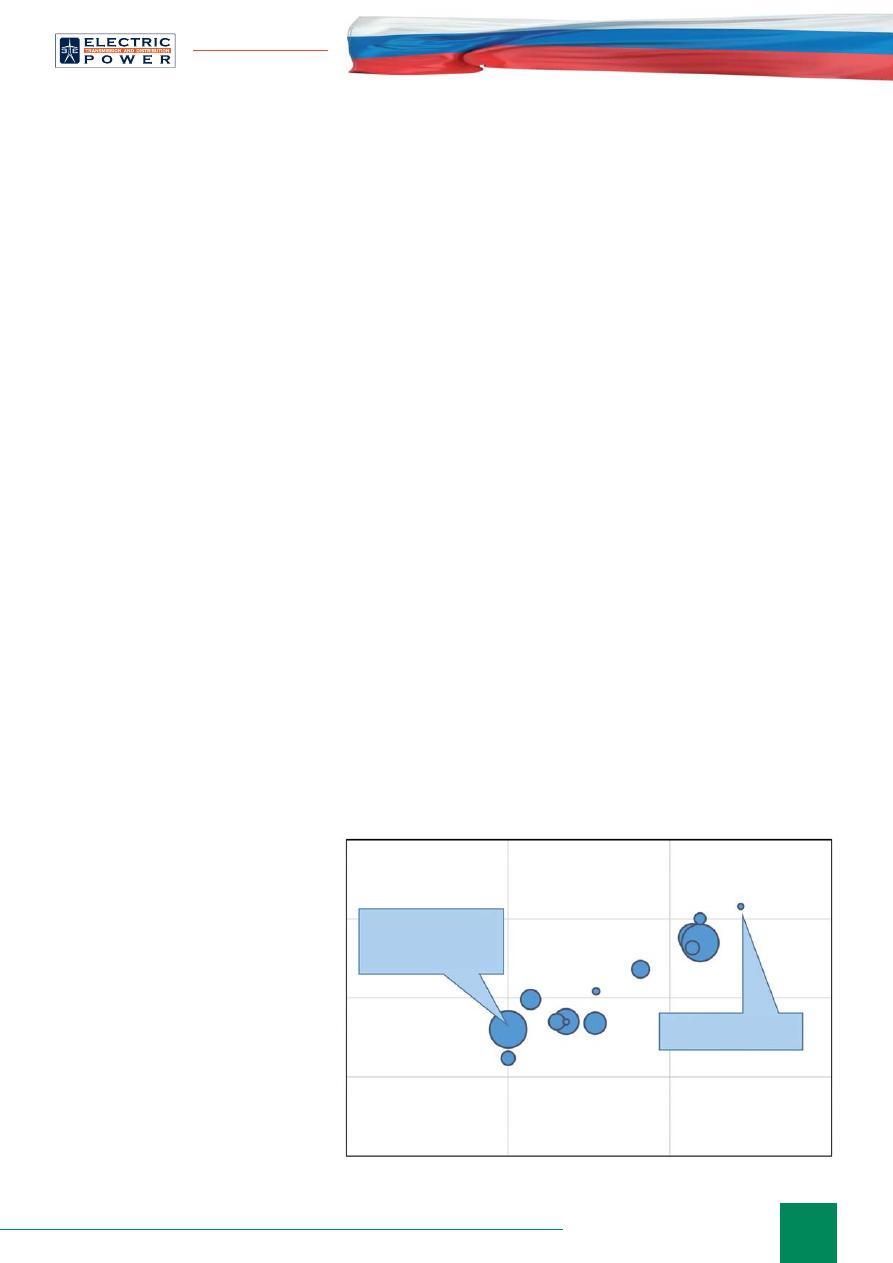
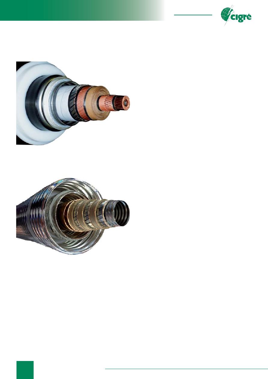
Among HTS conductors, several cable systems have
been designed and put in pilot operation in Germany, USA,
Korea, Japan and other developed countries (Fig.1, 2, 3).
Operation within a real grid demonstrates high reliability
of these systems.
An important factor enabling signi
fi
cant simpli
fi
cation
of HV insulation of HTS cables is very high dielectric
strength of liquid nitrogen, which is used as a cooling
agent (10—50 kV/mm, depending on pressure, nitrogen
purity and geometry). These values are comparable to
dielectric strength of transformer oil, which makes it
possible to greatly reduce the thickness of insulation layer
and HV cable size.
Main advantages of superconductive cable lines, in
addition to their compact size, are the following:
•
no electromagnetic
fi
eld outside the cable. As a rule
,
HTS cable design includes a shield of HTS tapes,
which prevents radiation from penetrating outside the
cable sheath. In particular, this enables laying HV CL
in ground;
•
no heat release
. Due to the fact that superconductor
operating temperature is extremely low, HTS cables
Fig. 1. AC HTS CL characteristics. Spot area is proportional
to the cable line length
AMPACITY project
Essen, Germany
10 kV/40 MVA/1000 m
Furukawa, Japan
275 kV/1500 MVA/30 m
1
10
100
1000
10000
1000
100
10
1
Voltage (kV)
Power (MV
A)
64
August 25–29, France, Paris
Innovations
have vacuum thermal insulation of a very high level.
Therefore, the temperature of cable system outer layer
approximates the ambient temperature. This makes it
possible to locate parallel cable HTS lines or phases in
close proximity to each other;
•
long service life
. The basic criterion that limits service
life of HV cables is insulation aging, which accelerates
at temperature rises (current increases). Since HTS
cables are operated at cryogenic temperatures, at which
negative insulation aging processes are very slow, the
expected service life of HTS CL exceeds service life of
standard cables many times.
Another useful property of HTS CL is relatively
low values of inductance and capacitance. Owing to it,
high power can be transmitted over HTS cables without
compensating devices for long distances (hundreds of
kilometers). In this regard, HTS CL is inferior only to an
overhead transmission line. Table 1 shows values of basic
parameters of OHL 380 kV, XLPE-insulation cable and
HTS cable, according to [1].
It should be noted that technologies of construction
of HTS cable systems have already been mastered in
Russia. In 2007—2010 a group of developers (JSC
“VNIIKP”, JSC “ENIN”, Moscow Aviation Institute,
JSC “R&D Center for Power Engineering”) designed
and manufactured an HTS cable, which at the time was
the longest in Europe (20 kV, 50 MVA, 200 m) [2]. JSC
“FGC UES” is vigorously developing a project of creating
the world’s longest DC HTS CL in St. Petersburg (20 kV,
50 MVA, 2500 m). Second-generation HTS conductors
are manufactured in CJSC “SuperOx”; in 2013 two model
cables with critical currents 3 and 4.5 kA were designed
in JSC “VNIIKP” on the basis of such conductors [3,4].
As applied to Moscow energy system, superconductive
cable lines can be implemented for introducing high power
to the city center with the use of existing infrastructure
or with its slight changes. For example, three phases
of a cable with operating voltage 275 kV developed by
Furukawa Company enable transmitting power of about
1500 MVA, and such a cable line can be placed in a cable
duct with 1 m width and 0.50 m height. The conductor
current-carrying capacity can be increased by using a
larger quantity of HTS conductor up to min.10 k
А
.
Thus, one can conclude that creation of a three-phase
AC HTS CL with operating voltage 220 kV and transmitted
power of 2000—3000 MVA is fully implementable
from the technical point of view. Such a line would be
a supercompact, energy-saving and ecological solution to
the above-described problem.
Development of electric energy systems (EES) is
closely related to the general economic development
and is characterized with sustainable growth of electric
loads, corresponding increase of generation capacities,
reinforcement of connections with adjacent EES
and creation of large interconnected systems, which
interconnect not only territories of separate countries but
also whole continents. An inevitable consequence of such
development is growth of short-circuit currents, which is
especially acute in high power consumption density areas
and metropolitan cities.
Another main problem related to grid operation in
Moscow energy system is high fault current values.
Calculations carried out in JSC “Energosetproyekt
Institute” showed that, with the existing grid
sectionalization, by 2020 fault currents in Moscow energy
system will exceed the following values:
• 63 kA on 16 existing and newly constructed energy
facilities 500 and 220 kV;
• 80 kA on 10 energy facilities 500 and 220 kV.
At present, the basic undertaking to limit fault currents
in Moscow energy system is sectionalization of the grid
110 and 220 kV.
A signi
fi
cant number of existing sectionalization points
of 110—220 kV grid and impossibility to increase the
Fig. 2. Phase of HTS cable manufactured by
Furukawa (Japan, 2013). Outer diameter 150
mm, voltage 275 kV, three-phase CL capacity
1500 MW
Fig. 3. Three-phase coaxial HTS cable 10 kV
manufactured by Nexans (Germany, 2014). Outer
diameter about 150 mm. CL capacity 40 MVA

65
info@eepr.ru, www.eepr.ru
number due to conditions of providing
reliable power supply of consumers
cause need in developing and taking
technical measures on limiting fault
currents.
Cost of a circuit-breaker with
operating breaking current 80 kA and
its size exceed the cost and size of
the existing circuit-breaker with rated
breaking current 63 kA almost twice,
which is a great obstacle for placing
such equipment at limited-space
substation sites in the city.
Thus, max. permissible level of
fault currents for Moscow energy
system should be 63 kA, and switching
equipment with rated breaking current
80 kA can be implemented only in
certain cases. Primary attention should
be paid to measures on limiting fault
currents.
Table 1. Comparison of characteristics of transmission lines
380 kV designed as OHL, XLPE-insulation cable and HTS CL
Parameter
OHL
XLPE-insulation
cable
HTS CL
Transmitted power, MVA
1645
1185
3290
Rated current, kA
2.5
1.8
5.0
Peak current, kA
3.0
—
10.0
Inductance, mH/km
0.879
0.470
0.215
Capacitance,
μ
F/km
0.0132
0.202
0.106
Resistance, mOhm/km
23.3
10.9
0.0004
Speci
fi
c impedance Z, Ohm
258
48
45
Load wave impedance (U2/Z),
MVA
559
2994
3200
Critical length
***
, km
2749
122
686
***
critical length is based on line speci
fi
c capacitive current values
Table 2. Technical and economic comparison of Moscow energy system development scenarios with
account for measures to limit fault current levels
Scenarios
Measures
Imple-
mentation
results
Negative sides
Need in CB
replacement,
pcs.
Imple-men-
tation cost,
million euro
Scenario 1 “Conventional”
Base-
case
variant
Installation of current-
limiting devices in
110 and 220 kV grid
40 kA and
below
No production of current-
limiters (CL) utilized
in the industry. No area
for placing CL at grid
facility sites
500 kV — 24
220 kV —199
110 kV — 491
720
Alterna-
tive vari-
ant
Creation of additional
sectionalization points
in 220 kV grid, installa-
tion of CLR in
110 kV grid
Increasing grid
sectionalization points
680
Balancing
Sectionalization of
Moscow City 110 and
220 kV grid into
4 parts
40 kA and
below
Decrease in reliability of
power supply of consum-
ers and power output of
power plants in repair
and post-emergency con-
ditions, need in ALT
500 kV — 24
220 kV — 117
110 kV — 378
500
External
Installing HVDC links
in OHL 500 kV inter-
connecting generation
facilities of IES of Cen-
ter and Moscow ring
500 kV substations
Redu-cing
fault currents
only in 500 kV
grid
No impact on fault
current levels in 220 and
110 kV grid
—
1800
HVDC links
and load
centers
Installing HVDC links
in 220 kV grid and
radial operation of
110 kV grid
Moscow—
40—50 kV,
Moscow
Region —
40 kA and
below
Need in extensive
territories for installing
HVDC links. Need in
ALT
500 kV — 22
220 kV — 145
110 kV — 407
1000
66
August 25–29, France, Paris
Innovations
Based on the conducted analysis of foreign experience
in construction of grids in metropolitan cities and
implemented methods and means of limiting fault current
levels, the following four scenarios of Moscow region grid
development with fault current limiting were developed:
conventional, balancing, external ones, HVDC links and
load centers.
Main results of technical and economic comparison
of the described scenarios of Moscow energy system
development with fault current limiting are shown in
Table 2.
The problem of limiting fault currents is relevant
for all countries of the world. Almost all large-scale
power engineering companies, international research
organizations such as CIGRE
и
IEEE, R&D centers and
higher educational establishments in many countries,
including Russia, try to solve this problem.
Development of new technologies and materials,
related to converter equipment and superconductivity
phenomenon, rapid progress in element base of power
electronics and high-temperature superconductive
materials (HTS) make it possible to develop current-
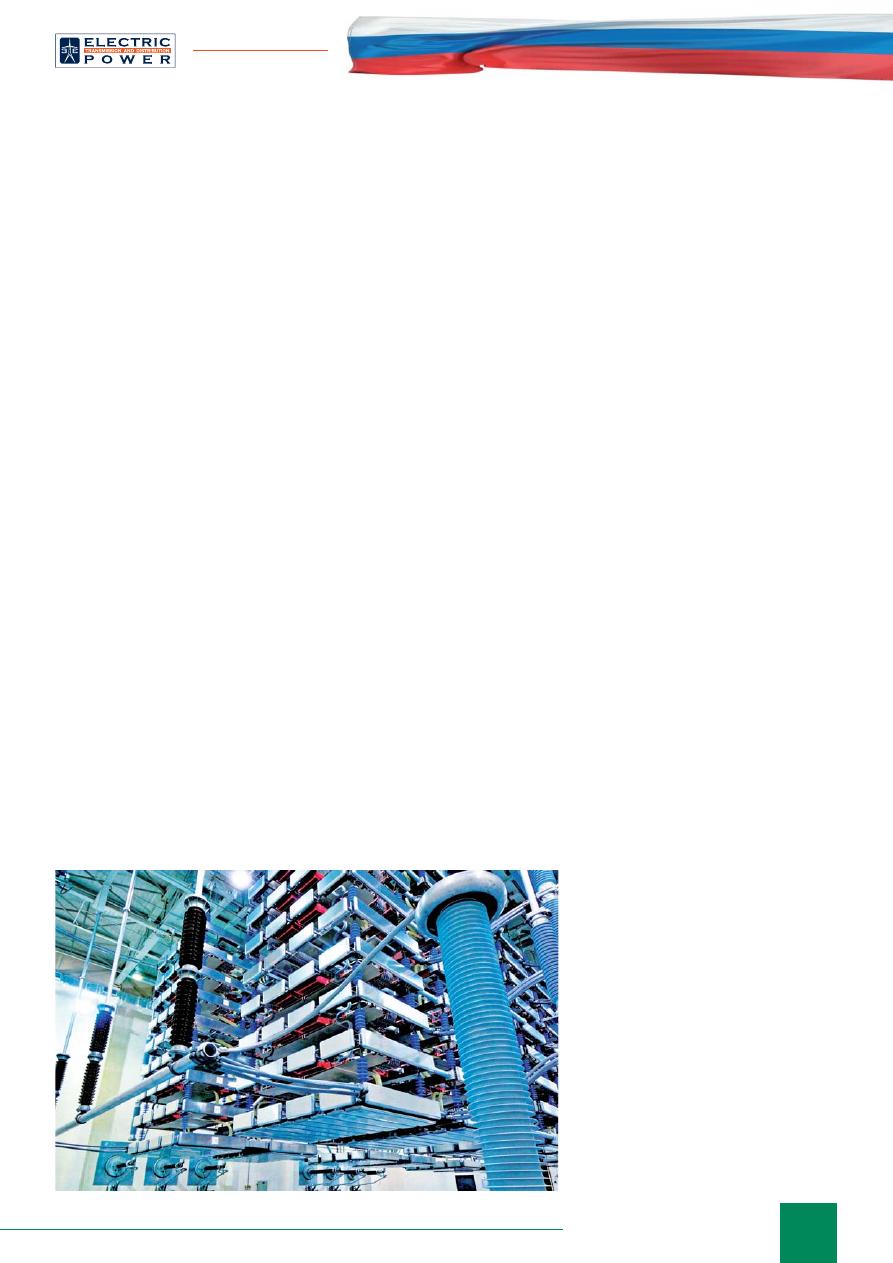
limiters (CL, Fig. 4), HVDC links and HVDC transmissions
(Fig. 5), FACTS, new-generation energy accumulators
with properties that give way to wide implementation of
such devices in power industry.
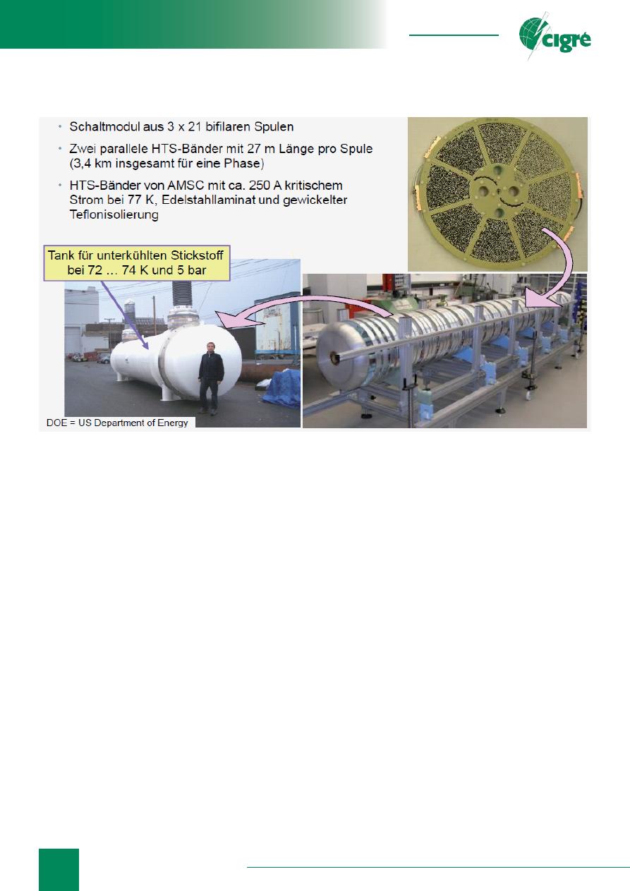
By present, more than 15 prototypes of superconduc-
tivity-based electrotechnical equipment for limiting of
fault currents have been designed and tested in the world.
Operation of these devices is based on the superconductor
property to transition from zero-resistance state into
fi
nite-
conductivity state when some speci
fi
ed critical current
value is exceeded. Transition from low-resistivity state
into high-resistivity one does not require external control
and happens very quickly (characteristic operation time
is about 1 ms), which is a key advantage of such systems.
Fault current limiters are actively developed in
Germany, Italy, USA, South Korea, China. For example, a
fault current limiter, designed for 24 kV/1 kA, was installed
in 2013 as a busbar switch 15 kV of adjacent transformers
on Majorca Island, Spain (ENDESA grid company); this
device was manufactured by Nexans Superconductors
(Germany). A fault current limiter, designed for
115 kV/900 A, was developed by Siemens (Germany),
now this device is in pilot operation in USA grid
(see Fig. 4). KEPRI, Korea, is designing a superconductive
current-limiter for 154 kV/2 kA to be installed in KEPCO
grid; its tests are scheduled for 2014. In China in 2011 an
HTS inductive fault current limiter, designed for 220 kV
and 800 A, was commissioned on Shigezhuang substation
(Tianjin).
As it was stated earlier, the issue of limiting fault
currents in 110 and 220 kV grids of Moscow energy
system is extremely acute. Therefore, implementation
of breakthrough technologies based on high-temperature
superconductors is especially relevant for Moscow City.
Installation of a current-limiting reactor (CLR) 220 kV
on “Mnevniki” substation was included in an investment
program of JSC “UNECO”. Projects of construction of
cable lines 220 kV also highlight the need in installing CL
Fig. 4. Components of CL superconductive switch 154 kV developed by Siemens
for the American energy system
67
info@eepr.ru, www.eepr.ru
on “Vagankovskaya”, “Novobrattsevo”, “Tsentralnaya”,
“Choboty” and other substations. JSC “UNECO” works
on the issue of installing a CL superconductive switch,
designed for 220 kV, on “Mnevniki” substation. Design
and integration issues were discussed with specialists
from Germany, South Korea and Russian company CJSC
“SuperOx”.
In conclusion, it should be stated that JSC “United
Energy Company”, while keeping to the line of sustainable
development of its power supply facilities, integration of
innovative technologies and equipment, participates, on a
permanent basis, in events that bring together Russian and
foreign power industry specialists.
JSC “UNECO” suggests further works on the issue
of construction of load-center substations fed by cable
superconductive lines 220 kV with capacity of 2—2.5
GW. With other conditions being equal, it is evident that
construction costs for 220 kV HTS CL will be lower due
to smaller sizes of cable tunnels.
Use of superconductive current limiters in 220 kV grid
will make it possible to solve the urgent problem related
to growth of fault currents in energy systems.
As part of its innovative activities, JSC “UNECO” also
intends to develop new projects based on implementation
of superconductive equipment, such as:
• superconductive energy accumulators with capacity
of 0.5—1.0 MW•h, for backup power supply of
residential consumers of metropolitan cities;
• construction of high-capacity grids 20 kV in Moscow.
Applied superconductivity has another, equally
important from the point of view of prospective
application
fi
elds, side, conventionally called low-
current applied superconductivity or superconductive
electronics. For example, with implementation of SQUIDs
(superconducting quantum interference devices), a new
generation of non-destructive evaluation magnetometering
systems, required, in addition to atomic, aviation and space
industries, for PD monitoring and diagnostics of insulation
structures in power engineering, is under development.
CONCLUSION
1. Technical grounds for implementing superconductivity
technologies in power engineering and power industry
have been well established by now.
2. Potential for wide implementation of energy-
ef
fi
cient superconductivity technologies is explained
by the fact that total losses at all stages (power
generation, distribution, consumption) can be reduced
2.5 times, with simultaneous reduction of consumption
of materials for devices and units 2—3 times
only by replacing conventional equipment with
superconductive one.
3. Implementation of the above described programs
requires developing
fi
nancial support models of
investment projects.
4. Taking into account the signi
fi
cance of superconductivity
technologies for a whole range of industries (power
industry, military equipment, transport, medicine,
megascience), a multi-target system of technology
development support with state participation should be
contemplated.
5. The task of developing superconductivity technologies,
being an integral part of the innovative constituent of
Russian power industry development, is relevant and
requires immediate solution.
REFERENCE LITERATURE
1.
R. Zuijderduin, O. Chevtchenko, J.J. Smit,
G. Aanhaanen, I. Melnik, A. Geschiere, AC HTS
transmission cable for integration into the future EHV
grid of the Netherlands, Physics Procedia 36 ( 2012 )
1149—1152.
2. V.S. Vysotsky, A.A. Nosov, A.V. Rychagov, V.E.
Sytnikov, S.S. Fetisov, K.A. Shutov, Development of a
superconductive power cable based on
HTS technologies. Project development
and results, Cables and Conductors,
2010,
№
3, p. 3.
3.
S. Lee, V. Petrykin, A. Molodyk,
S. Samoilenkov, A. Kaul, A. Vavilov, V.
Vysotsky, S. Fetisov, Development and
production of second generation high Tc
superconducting tapes at SuperOx and
fi
rst tests of model cables, Supercond.
Sci. Technol. 27 (2014) 044022.
4.
.S. Vysotsky, S.Yu. Zanegin, V.V.
Zubko, A.A. Nosov, G.G. Svalov, S.S.
Fetisov, S.R. Lee, S.V. Samoylenkov,
First models of current-carrying
conductors of superconductive cables
manufactured with the use of Russian
second-generation HTS tapes and
results of their tests, Cables and
Conductors, 2013,
№
6, p. 26.
Fig. 5. Components of an HVDC link
Оригинал статьи: Prospects of Implementation of Electrotechnical Equipment with Superconductivity Technology Elements in JSC “UNECO”
Moscow energy system supplies power to consumers in the territory of Moscow City and Moscow Region, with the total area of 47 000 m2 and population of over 19 million people.