
The MAIN JOURNAL for POWER GRID SPECIALISTS in RUSSIA

26
August 25–29, France, Paris
Grid Control
Multifunctional bay controller
ARIS C303
Fig. 1. Front panel control and indication elements
T
o develop a controller with a unique set of
functions, which is capable of operating in
harsh environments (wide temperature range,
electromagnetic interferences, etc.) as well as
simple to use, is a dif
fi
cult job.
Lots of details await you on the road to the ready-to-use
product, which purpose is to perform speci
fi
c monitoring
and control functions in electric power systems. All the
requirements have to be taken into account, precisely
re
fl
ected in product technical speci
fi
cations and thoroughly
implemented by the development team.
Developers must thoroughly plan hardware and
software product architecture. If support of proprietary
communication protocols is in plans, revision control and
software updates systems have to be implemented too.
This article is a result of our test of one of
multifunctional intelligent electronic devices with IEC
61850 implementation — ARIS C303 bay controller,
produced by the company Prosoft-Systems.
PRODUCT DESIGN
Once you get to know ARIS C303, you’ll never mix it
up with any other product: angular 19
″
enclosure, black
mat front panel, 5.7
″
high-resolution display (capable of
visualizing animated single-line diagrams), keyboard and
switchgear control mode selection switch (Fig.1).
Front panel also includes service interfaces and LED
indication elements. Everything looks neat and clean.
Introducing settings via integrated keyboard is an easy
thing to do. IED has modular design with 14 slots for
modules’ installation. Access to these slots and their
interface is available from the back side.
MODULES,
MODULES, MODULES…
Besides one or two power supply modules and one or
two processor boards, ARIS C303 can be equipped with
up to 14 modules of different functionality:
• CT/VT direct connection modules, implementing
measurement and waveform recording functions;
• IEC 61850-9-2LE modules, allowing to receive up to
4 Sampled Value streams, implementing measurements
and waveform recording functions;
• RS-485, RS-232 and Ethernet communication
interfaces modules;
• 24 V (8- or 15-channel) or 220 V (7- or 15-channel)
binary input modules;
• 220 V binary input modules with operation voltage
setting and rejection functionality
(15-channel);
• 24 V (8-channel) or 220 V
(8-channel) binary output modules;
• Analog current input modules
(0—5 mA, 4—20 mA, 0—20 mA);
• Analog voltage input (0—1 V,
0—5 V, -10 —+10 V, 0—10 V);
• Remote control modules with
support of select before operate
functionality (220 V).
The tested ARIS C303
was equipped with two 220 V
15-channel binary input modules
and 220 V 8-channel binary output
modules, one 8-channel analog
Alexander GOLOVIN (
Александр
ГОЛОВИН
),
Alexey ANOSHIN (
Алексей
АНОШИН
)
Engineering company TEKVEL Ltd.
27
info@eepr.ru, www.eepr.ru
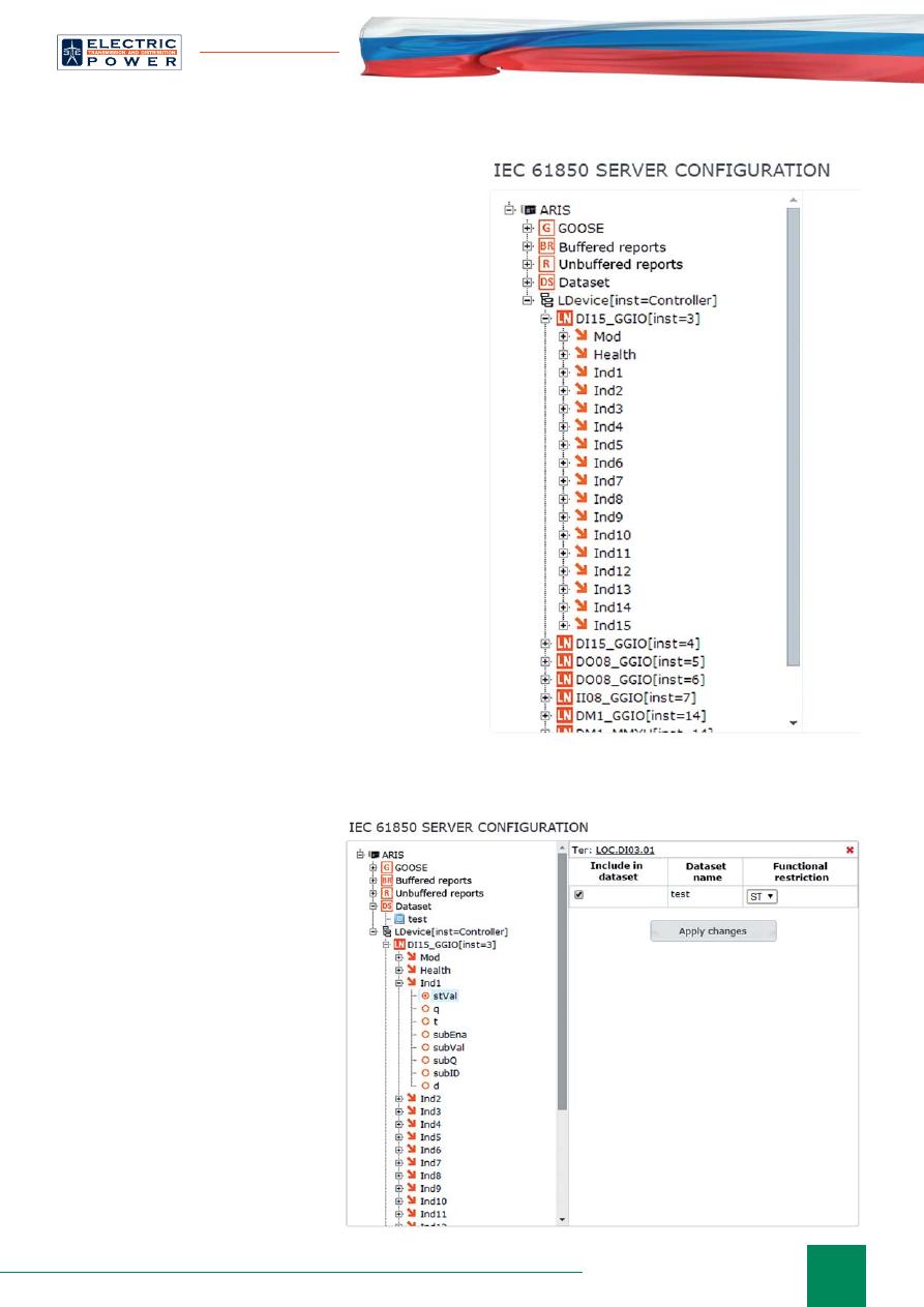
Fig. 2. IED information model
Fig. 3. Creation of a dataset
signal input module and one measurements and waveform
recording module with capability of direct connection
to current and voltage transformers. IED also included
the following basic modules: power supply module and
processing board with GPS/GLONASS receiver.
Processing board provides time synchronization
functionality. There is an integrated GPS/GLONASS
receiver inside and if you connect an antenna to it, IED will
be time synchronized. Alternative solution to provide time
synchronization of the device is time synchronization over
NTP or by using Prosoft GPS Module external precision
time source, which is connected to RS-485 port of IED.
ARIS C303 may also be an NTP-server.
ARIS C303 is capable of operating in harsh
environmental conditions, withstanding electromagnetic
interferences according to IEC 61850-3 and wide
temperature range (from -40 to +55°
С
). Equipment,
developed at Prosoft-Systems, is tested on electromagnetic
immunity and safety. Primary calibration of devices is
also performed in the Prosoft-Systems labs.
FUNCTIONALITY
ARIS C303 provides rich functionality as well.
Interlocking and user-de
fi
ned algorithms (implemented
using Function Block Diagram language), metering and
waveform recording functions are available for use.
Data transmission and reception is possible using
variety of communication protocols: IEC 61850, 60870-
5-101/104/103, Modbus (RTU/ASCII/TCP), SPA and set
of proprietary communication protocols.
IEC 61850
IMPLEMENTATION
Let’s take a closer look at the IEC
61850 implementation. Information
model (Fig. 2) is dynamic. It
changes depending on the set of
modules installed. Each logical node
corresponds to the speci
fi
c module.
Number of logical node data objects
depends on the number of input/
output channels of the module. User
won’t feel that it’s dynamic from
the very beginning — IED comes
precon
fi
gured at the factory. But
once there’s a need to change the set
of preinstalled modules, it could be
noticed. To represent status signals, are
used GGIO logical nodes. Switchgear
and measurement functions are
represented by appropriate standard
logical nodes (XCBR, XSWI,
MMXU, etc).
The following communication
services are supported:
• GOOSE
publisher/subscriber;
• IEC 61850-9-2LE Sampled Value
28
August 25–29, France, Paris
Grid Control
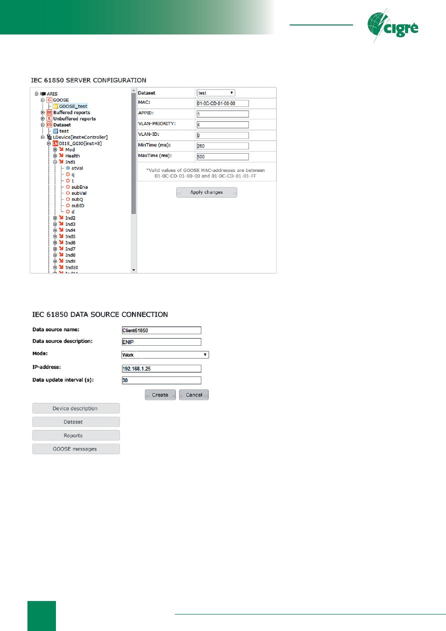
Fig. 4. GOOSE control block con
fi
guration
Fig. 5. Reading server con
fi
guration data over
MMS
subscriber (of up to 4 80 samples/cycle or 256 samples/
cycle streams);
• Client-server functionality — IED can take roles of
both client and server (supporting buffered/unbuffered
reporting).
CONFIGURATION
INTERFACE USABILITY
When an IP address of the speci
fi
c IED is set in web
browser and authorization is successful, user sees nicely
looking main page of ARIS C303 web interface.
Main menu has seven items in the form of drop-down
lists, located on the top of the page. These menu items are
also available in a tree view and may
be visualized when
Do you want to
see the list of all available services?
link is selected.
First of all, let’s evaluate usability
of IEC 61850 communications
con
fi
guration procedure.
Con
fi
guration of GOOSE
publishing and reporting is quite
standard and intuitive. First, user has
to create a dataset. To do this, it is
required to make a right click on the
datasets menu item and choose
Add
dataset
option. Required information
model data objects/attributes are
added to the dataset (Fig. 3). To
select speci
fi
c data, user navigates
through information model tree and
checks
Add to dataset
menu item
for all required elements. It’s quite
convenient, though you have to
con
fi
rm selection of each and every
data object/attribute by choosing
Apply changes
menu item.
If it is required to con
fi
gure IED for publishing
GOOSE messages, GOOSE control block must be
created. This process is similar to the creation of the
dataset (Fig. 4). When GOOSE control block is created,
user needs to open its structure and set parameters.
Everything is easy and intuitive here. Speci
fi
c dataset may
be selected from the drop-down list. It’s nice that control
block con
fi
guration procedure is accompanied by a tip,
regarding Destination MAC address acceptable range.
It makes you remember about this parameter, which is
quite important when multicast
fi
ltering is implemented
on substation LAN. It’s also easy to con
fi
gure buffered
and unbuffered report control blocks.
Now let’s look at the several drawbacks, which we’ve
found. First, it’s impossible to set BufTm parameter
for unbuffered report control block. It seems to be a
misunderstanding, because in fact this parameter doesn’t
have to do anything with buffering of reports but de
fi
nes
time interval, over which all occurred events are included
in the single report. BufTm parameter must be available
for both buffered and unbuffered report control blocks.
We’ve also noticed that naming of several optional
fi
elds that may be included in report is not correct: for
example, instead of data-reference optional
fi
eld control
block reference
fi
eld is available, though the latter is not
there in the standard.
Talking about data reception con
fi
guration procedure
— it is straightforward. It’s required to set IP address of
the server under the
Data reception
menu item. Then user
has to select
Create
menu item (Fig. 5).
ARIS C303 will read server con
fi
guration over MMS
and information model of the server will be available
for overview under
Device description
menu item
29
info@eepr.ru, www.eepr.ru
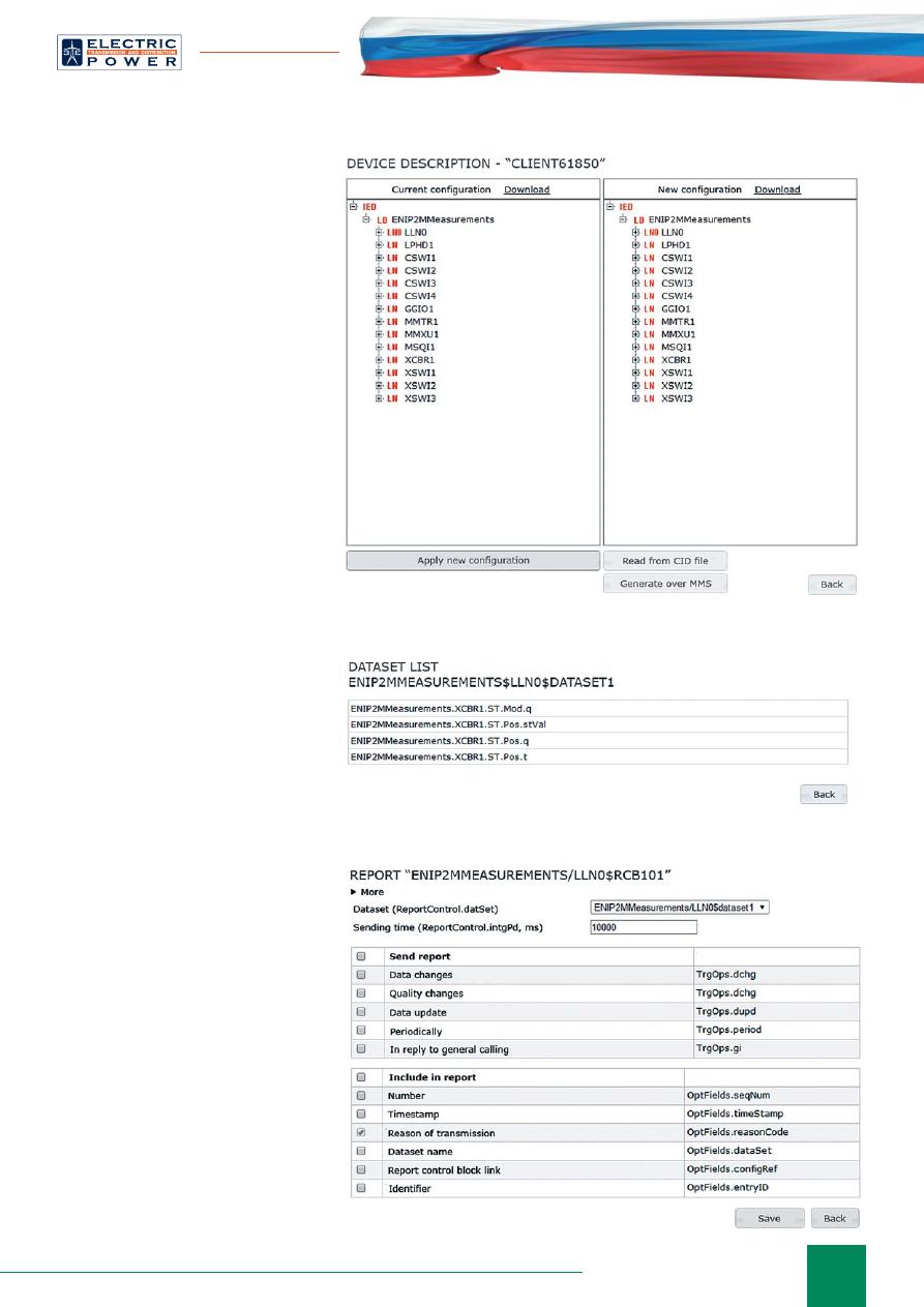
Fig. 8. Server report control block con
fi
guration
Fig. 6. Visualization of server information model
Fig. 7. Server datasets
(Fig. 6). There user can also generate
CID
fi
le of the server based on the
presented structure.
Then it will be possible to
overview datasets (Fig. 7), as well
as report and GOOSE control blocks
available on the server.
To be able to receive data using
one of the IEC 61850 communication
services (either reporting or GOOSE
messaging) it is required to choose
either
Reports
or
GOOSE messages
menu item, check appropriate control
block and choose
Apply
menu item.
For reporting it is required to set
trigger options and de
fi
ne optional
fi
elds which will be included in report
along with the data (Fig. 8).
For GOOSE messages user may
create service data channels. This
will activate calculation of missed
messages, visualization of status id,
message sequence number, etc. This
data will be further available for use.
Data reception con
fi
guration is
done in one click.
To apply con
fi
guration changes it
is required to restart controller. While
you’re waiting, on the screen will be
shown useful tips on how to operate
controller.
Data reception con
fi
guration
procedure has the same drawbacks
as data transmission con
fi
guration
procedure. For unbuffered reports it’s
impossible to set BufTm parameter,
because there is no such
fi
eld. The
same issues reside in optional
fi
elds
settings.
In general, ARIS C303
con
fi
guration interface usability is
thought-out and well done.
FINAL THOUGHTS
ARIS C303 bay controller is a
worthy representative of micropro-
cessor-based devices, developed and
manufactured in Russian Federation.
It shows good results in all disci-
plines: design, ergonomics, func-
tionality, and web interface usability.
Everything is at a good level. Not
every product can be described in this
way. It’s obvious that a great number
of engineers has been working on the
product. And this means that minor
drawbacks will be
fi
xed soon.
Оригинал статьи: Multifunctional bay controller ARIS C303
To develop a controller with a unique set of functions, which is capable of operating in harsh environments (wide temperature range, electromagnetic interferences, etc.) as well as simple to use, is a difficult job.