
The MAIN JOURNAL for POWER GRID SPECIALISTS in RUSSIA
3 - 6 J U N E 2 0 1 9
MADRID, SPAIN
30
Effi
ciency of Implementing
Domestic Innovative High-
strength and High-temperature
Steel-Aluminum Сonductors
PJSC "Rosseti" maintains 44 thousand km of new conductor
types or 1% of the total conductors' length (4.5 million km).
Self-supporting insulated wires of various modi
fi
cations (more than
41 thousand km or 0.9% of the total conductors' length) and bare
conductors (less than 3 thousand km or less than 0.1% of the total
conductors' length) are among these conductors. In addition,
Russian modern power grid is characterized by physical deteriora-
tion and obsolescence of equipment. As a result, low energy ef
fi
-
ciency of power facilities takes place. The most important indica-
tor of power system ef
fi
ciency is the level of energy losses. With
the growing power losses in electrical networks, the number of
urgent problems increases. Reconstruction and technical re-equip-
ment of electrical networks, application of advanced technical
developments in design solutions, implementation of modern tech-
nologies and materials increasing reliability, durability and main-
tainability of power transmission lines are among these problems.
Fokin V.A.,
Director General of
"Energoservis", LLC
Timashova L.V.,
Ph.D., Principal researcher of
the Department for Supporting
Scientifi c and Technical Council
and Scientifi c and Technical
Information, "R&D Center "FGC
UES", JSC
Merzlyakov A.S.,
Head of the Center for
Composite Materials and
Superconductivity, "R&D Center
"FGC UES", JSC
Gurevich L.M.,
D.Sc., Head of the Department
of Materials Science and
Composite Materials, VSTU
Kuryanov V.N.,
Ph.D., Head of Power and
Electrical Engineering
Department, National Research
University "Moscow Power
Engineering Institute"
Nazarov I.A.,
Head of the Substation
Department of the Center
for Reliability and Asset
Management, "R&D Center
"FGC UES", JSC
INTRODUCTION
As of today, fi nding the ways for improving pow-
er grid energy effi ciency is a pressing issue. One
of the ways is the use of innovative conductors
with better characteristics than steel-aluminum
conductors. Increased transmission capacity,
mechanical strength, resistance to high tem-
peratures and resistance to aging and aggres-
sive ambience are among these characteristics.
Power losses optimization in electrical net-
works requires accelerated implementation of
the following activities:
– upgrading power grid equipment and imple-
mentation of new energy-saving technolo-
gies;
– conducting research, design and develop-
ment works related to calculations, analysis,
rationing and reduction of power losses in
electrical networks.
The paper systematizes studies carried out
in the framework of the project for developing
high-temperature and high-strength conductors
according to the relevant Agreement with PJSC
"Rosseti". The task of the studies was to con-
fi rm the possibility of solving the basic problems
of overhead lines construction and operation
through the joint use of ASHT/ASHS conduc-
tors together with overhead ground wires, when
keeping cost at a level of steel-aluminum con-
ductors. The results are shown in table 1 and
described in this paper.
o
v
e
r
h
e
a
d
t
r
a
n
s
m
is
s
io
n
l
in
e
s
overhead transmission lines
3
1
RESEARCH OF CORONA DISCHARGE OCCURRENCE AS A FUNCTION OF VOLTAGE
An important point when using conductors with less di-
ameter is the risk of corona losses and noise level en-
hancement. "R&D Center "FGC UES", JSC
and then VDE (Verband der Elektrotechnik,
Elektronik und Informationstechnik) con-
ducted four studies for testing this problem.
At the fi rst stage, two conductors of the same
diameter (18.8 mm) were taken for comparing
and studying corona discharge. In total, four
conductors were used within the experiment
(Table 2). The tests were carried out in ac-
cordance with IEC 61284 recommendations.
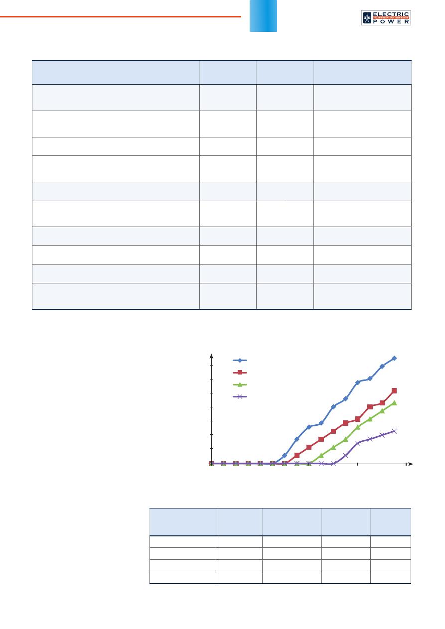
Based on comparative tests results ob-
tained at "FGC UES" R&D Center, it was es-
tablished that ASHS 197/55 conductor manu-
factured by "Energoservis", LLC has corona
discharge voltage (142.2 kV) by 5.7% higher
than ACSR 185/29 conductor (134.5 kV) with
the same diameter (18.8 mm).
Similar tests were carried
out for ASHS 216/33 and ACSR
240/32 conductors with diff erent
diameters. Based on compara-
tive tests results ACSR 240/32
conductor (21.6 mm in dia meter)
and ASHS 216/33 conductor
(18.5 mm in diameter) have
the same corona discharge
voltage. However, continuous
permissible current of the con-
ductors being compared diff ers signifi cantly (510 A for
ACSR 240/32 conductor, 689 A for ASHS 216/33 con-
ACSR150/19
ACSR185/29
ASHS197/55
ACSR240/32
Table 1. Possibilities of solving the main problems of overhead lines
construction and operation through the joint use of ASHS / ASHT conductors
Problem
Solution
based on ACSR
application
Solution based
on ASHS / ASHT
application
Confi rmation
Reducing corona losses and noise level, without
increasing conductor’s diameter
–
+
Experimental confi rmation of
"R&D Center "FGC UES", JSC
and VDE (Germany)
Increasing lightning protection and resistance to short-
circuit currents
–
+
Experimental confi rmation of
"R&D Center "FGC UES", JSC
and VDE (Germany)
Signifi cant reduction of elongation in operation
–
+
Experimental confi rmation of
"R&D Center "FGC UES", JSC
Reducing vibration, galloping and oscillations self-
damping, while keeping conductor diameter
–
+
Experimental and computa-
tional confi rmation of VSTU,
JSC "VNIIZHT" and MPEI
Increasing span length and (or) sags, without increas-
ing conductor’s diameter
–
+
Design solutions
Replacing the conductor on the existing transmission
poles, decreasing the load on all elements of overhead
line and (or) increasing its transmission capacity
–
+
Design solutions
Decreasing wind pressure while keeping conductor
diameter
–
+
Computational confi rmation of
VSTU and MPEI
Replacing the conductor in the ring networks and
decreasing conductor diameter
–
+
Design solutions
Reduction of icing, while keeping conductor diameter
–
+
Computational confi rmation of
VSTU and MPEI
Keeping transmission capacity in areas with high air
temperatures and solar activity, without increasing
conductor’s diameter
–
+
Design solutions and compu-
tational confi rmation of VSTU
and MPEI
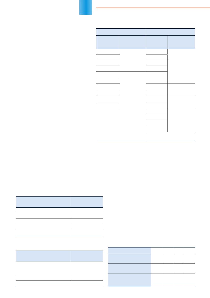
Table 2. Technical data of the tested conductors
Conductor model
Conductor
diameter
(external), mm
Number of alumi-
num wires in the
conductor, pcs
Diameter of
outer layer
wires, mm
Continuous
permissible
current
ACSR 150/19
16.8
24
2.8
450
ACSR 185/29
18.8
26
2.98
510
ASHS/ASHT 197/55
18.8
28
3.45
561/943*
ACSR 240/32
21.6
24
3.6
605
* t
max
= 70 °C for high-strength steel-aluminum conductors and t
max
= 150 °C for high temperature
steel-aluminum conductors.
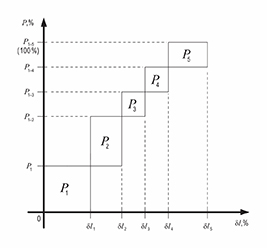
Fig. 1. Dependence of corona discharge points number on voltage
Corona discharge points number
, pcs
Voltage, kV
100
160
180
120
140
30
25
20
15
10
5
0
24th World Energy Congress
Special issue, September 2019
32
ductor (t = 70 °C), and 1040 A for ASHT 216/33
conductor (t = 150 °C)).
The test voltage for inspecting visible corona
on 220 kV overhead lines was determined by
FGH Engineering & Test GmbH laboratory as
167.7 kV (phase voltage). The test voltage of
"R&D Center "FGC UES", JSC laboratory was
160.0 kV (phase voltage).
The test procedure in both laboratories was
identical. Voltage levels and registered results
when testing visible corona are shown in Table 3.
The tests of new ASHT 216/33-1 high-tem-
perature conductor for visible corona inception
were carried out in "FGC UES" R&D Center na-
tional testing laboratory and FGH Engineering &
Test GmbH German testing laboratory. The tests
were performed according to IEC 61284:1998
method and produced similar results for corona
ignition voltage and streamer inception of coro-
na discharge.
The diff erences in the results occur due to
the conditions of conductor samples when test-
ing. Conductor samples were taken directly from
the drum when testing in FGH Engineering & Test
GmbH laboratory. As to the tests of "FGC UES"
R&D Center laboratory, the surface of conduc-
tor samples was additionally cleaned of dirt and
small defects (related to the transportation and
unwinding) that could cause corona discharge.
It was done for studying immunity of new ASHT
19.6-216/33-1 conductors to corona discharge inception.
According to the tests results obtained by the labora-
tories, it was determined that streamer inception of co-
rona discharge for ASHT 19.6-216/33-1 conductor is at
the level of 139.7-150 kV (phase voltage). Based on co-
rona discharge level, this conductor is recommended for
use in domestic and foreign 110, 115, 138 and 150 kV
electrical networks (in some cases the conductor can be
used up to 220 kV).
The calculated specifi c corona losses in good weath-
er are presented in Tables 4, 5. Table 6 gives the aver-
age characteristics of overhead transmission lines in
Russia.
ASHS conductors have advantages in terms of
smaller corona losses in comparison with ACSR con-
ductors of the same diameter. Also, ASHS conductors
have comparable corona losses in regard to ACSR con-
ductors with larger diameter and similar electrical and
mechanical characteristics.
STUDY OF WIND PRESSURE
The direct infl uence of wind on overhead lines opera-
tion is its pressure on the conductors, ground wires and
poles. In addition, wind increases conductors' tension
through creating a transverse load. Additional bending
forces on power line poles also appear. Wind pressure
can cause breakage and fall of the poles with the pull out
of bad fi xed foundations. The results given below proves
the necessity of replacing ACSR conductors with ASHS/
ASHT ones on obsolete overhead lines.
Table 3. Results of visible corona discharge registration
for ASHT-216 / 33-1 conductor
FGH Engineering & Test GmbH "R&D Center "FGC UES", JSC
Test
voltage, kV
Presence of
visible corona
discharge
Test
voltage, kV
Presence of
visible corona
discharge
41.9
Absence of
visible corona
discharge
100.0
Absence of
visible corona
discharge
55.9
105.0
70.0
110.0
83.8
115.0
97.8
Corona ignition
voltage
120.0
111.8
125.0
125.7
130.0
Scant glow of
isolated corona
discharge points
139.7
Streamer incep-
tion of corona
discharge
135.0
153.7
140.0
Stable ignition of
corona discharge
167.7
Increment — 10% of rated test
voltage 167.7 kV (phase voltage)
150.0
Streamer
inception
of corona
discharge
155.0
160.0
165.0
Increment — 5 kV of rated test
voltage 167.7 kV (phase voltage)
Table 4. Calculated specifi c corona losses in good weather
(220 kV overhead line)
Phase construction (conductor
model; conductor diameter)
Annual average
losses change
ACSR 240/32, Ø 21.6 mm
+ 26.67%
ACSR 300/39, Ø 24.0 mm
0.00%
ACSR 330/43, Ø 25.2 mm
–13.33%
ASHS 317/47,
Ø 22.3 mm
–13.33%
ASHS 295/44,
Ø 21.5 mm
–6.67%
Table 5. Calculated specifi c corona losses in good weather
(330 kV overhead line with split phase
consisting of 2 conductors with 40 cm spacing)
Phase construction (conductor
model; conductor diameter)
Annual average
losses change
2 × ACSR 300/39, Ø 24.0 mm
+ 18.52%
2 × ACSR 400/51, Ø 27.5 mm
0.00%
2 × ASHS 317/47,
Ø 22.3 mm
–7.41%
2 × ASHS 295/44,
Ø 21.5 mm
+ 3.70%
Table 6. Average characteristics of overhead lines in Russia
Voltage. kV
220
330
500
750
Average length of over-
head line. km
59
88
187
250
Average diameter of
ACSR conductor. mm
25.6
25.6
27.4
26.1
Possible ASHT / ASHS
conductor diameter in
terms of corona discharge
22.4
22.4
24.5
24
OVERHEAD
TRA
N
SM
I
SS
I
O
N
L
IN
ES
33
COMSOL Multiphysics software package was used
for simulating airfl ow behavior near the conductors. The
software allowed engineers to solve partial diff erential
equations. Navier-Stokes equation was the model basis:
(
u
·
)
u
=
·
–
Pl
+ (
+
T
)(
u
+ (
u
)
T
) –
2
2
– — (
+
T
) (
u
· )
l
– —
kl
+
F
,
3
3
·
(
u
)
= 0,
(
u
·
)
k
=
·
(
+
T
k
*
) (
k
)
+
P
k
–
0
k
,
(1)
(
u
·
)
=
·
(
+
T
*
) (
k
)
+
a
(
/
k
)
P
k
–
0
2
,
T
=
k
/
,
2
2
P
k
=
T
·
u
: (
u
+ (
u
)
T
) –
—
(
·
u
)
2
– —
k
·
u
,
3
3
where
u
is the air velocity; is the del operator;
is the
air density;
is the dynamic viscosity;
k
is the turbulent
kinetic energy;
is the specifi c dispersion rate;
a
,
*
,
k
*
,
0
,
0
are the coeffi cients of turbulent fl ow,
l
is the
turbulence intensity.
The two-dimensional model was used to assess the
wind impact on conductors with diff erent cross-sectional
shapes. The model’s geometry is shown in Figure 2.
The following boundary conditions were chosen:
– wind speed direction is perpendicular to AB:
AB
=
0
;
(2)
– pressure equals zero on BC, CD and AD faces:
p
= 0 ;
(3)
– the boundaries of conductor’s cross section are non-
deformable walls.
The simulation was carried out at diff erent values of
AB
speed, which are typical for I, III and special wind
zones according to 7th edition of Electrical Installations
Code [1].
The wind load acting on the
conductor across the center
was calculated as the sum of
pressure X-components:
F
=
∫
n
·
P dl
,
(4)
where
P
is pressure,
n
is the unit
vector along the
X
-axis.
The interactions of wind and
conductors depending on wind
speed and type of conductors'
cross-section have been com-
pared. The following conductors
with similar diameters have been
used for comparison: ASHS
128/37 and ACSR 120/19; ASHS
230/32 and ACSR 240/34; ASHS
277/79 and ACSR 240/56 (the
cross-section area of aluminum
and steel in mm
2
represent in
the numerator and denomina-
tor respectively). The calculated
wind load diff ers from
P
H
W
, stan-
dard wind load on conductors
and ground wires, determined
according to 7th edition of Elec-
trical Installations Code. The diff erence takes place due
to ignoring the following facts: wind pressure change at
various heights depending on terrain, the infl uence of
span length on the wind load, wind pressure nonunifor-
mity along overhead line span. The used approach allows
engineers to determine clearly the contribution of conduc-
tor’s contour to the change of wind load.
The view of conductors' contour after crimping was
obtained by modeling steel-aluminum conductor plastic
deformation process in the Abaqus/Explicit module of
the SIMULIA/Abaqus software (Abaqus, Inc., USA). For
all ASHS conductors aluminum wires of outer layer are
tightly adjacent to each other without gaps. It provides
a possibility to simulate the wind impact on a single con-
ductor with one external contour by means of COMSOL
Multiphysics.
The wind pressure acting on the conductors and
air velocity distribution after fl owing around ACSR con-
ductors (according to GOST 839) and ASHS conduc-
tors (according to STO 71915393 – TU 120-2012) with
230 mm
2
aluminum cross section are shown in Figures
3 and 4. A smoother contour and the smaller diameter
of ASHS conductors provide the reduction of pressure
zone in front of the conductor (Figure 3b) and the stag-
nant zone behind
it (Figure 4b). The
maximum pressure
on ASHS conduc-
tors is less by 3.5%,
while the area with
increased pressure
is smaller regarding
to ACSR conduc-
tors. The formation
of several local ar-
eas characterized
by air deceleration
Fig. 2. Geometry of the used model:
1 – conductor cross-section,
2 – air
fl
ow
Fig. 4. Speeds distribution in the air
fl
ow at the wind speed of 25 m/s (the
fi
rst wind
zone): a) ACSR 120/19; b) ASHS 128/37
а)
а)
b)
b)
Fig. 3. Wind pressure acting on the conductors at the wind speed of 60 m/s (the
fi
rst wind
zone): a) ACSR 400/64; b) ASHS 477/66
Wind pressure, kPa
Air speed, m/s
mm
mm
mm
mm
mm
mm
mm
mm
24th World Energy Congress
Special issue, September 2019
34
and reduced pressure is much more visible on the pro-
truding turns of ACSR aluminum wires facing airfl ow front.
As can be seen from the data above, wind load on
ASHS conductors having streamlined design is lower by
33% on the average. Reduction of wind load makes it
possible to reduce the load on power transmission poles
and to mount conductors with greater transmission ca-
pacity on existing poles during capital repairs. Also, the
possibility to reduce the load on all elements of overhead
line when keeping its transmission capacity appears.
REDUCTION OF VIBRATION LOADS
AND OPERATING TENSION
Plastically crimped conductors have a number of advan-
tages, which are usually typical for expensive conduc-
tors from profi led wires. Among these advantages are
vibration loads reducing and oscillations self-damping.
Intensive gust-and-glaze loading of 6-750 kV over-
head power lines is one of the urgent power industry
problems in the countries with relevant weather condi-
tions. Plastically deformed ASHS conductors have al-
most smooth outer surface (close to conductors from
segmented
- and Z-shaped aluminum wires). Due to
this, conductors vibration and galloping as well as ice
coating can be reduced. At the same time, ASHS con-
ductors should have greater torsional rigidity, reduced
galloping probability, increased resistance to vibration,
and self-damping ability even in comparison with con-
ductors from segmented
- and Z-shaped aluminum
wires, because ASHS conductors have developed con-
tact surface of adjacent wires not only inside one layer,
but also between layers [2].
Plastic deformation of conductors not only increases
the mechanical strength signifi cantly, but also several
times reduces elongation during operation (regardless
of the metal). The corresponding tests with products
from diff erent metals (from steel to copper) were carried
out in JSC "VNIIZHT" and "R&D Center "FGC UES",
JSC. Complete study is presented in [3].
INCREASE OF SPAN LENGTH WHEN
CONSTRUCTING NEW FACILITIES
The plastically crimped ASHS and ASHT conductors
allow engineers to increase the distance between
overhead line poles up to 40% of the standard span
(in the absence of restrictions related to line route).
It is an urgent task when constructing new overhead
lines. For example, the comparative analysis of the
span length for ASHS 128/37 conductor mounted on
110 kV overhead line and ACSR 120/27, TACSR 120,
ACSR 120/19 conductors with the same cross-section
and dia meters has been fulfi lled. Because of ASHS
128/37 conductors application the span length can be in-
creased from 212 to 294 m compared with ACSR 120/27
conductor. ASHS 128/37 conductor has a higher content
of steel (the ratio between aluminum and steel cross-sec-
tion area is 3.45 for ASHS 128/37 conductor and 4.3 for
ACSR 120/27 conductor), an equal diameter (15.2 mm),
and increased transmission capacity (by 8% higher).
An example of ASHS/ASHT conductors application
effi ciency is the initial project of 150 kV Murmanskaya
overhead line (Table 8 and Figure 5). ASHS 258/73 con-
ductor is the most eff ective option when constructing
new overhead line. In its turn, ASHS 216/33 conductor
is the optimal option when reconstructing overhead line
(replacing conductors on existing power transmission
poles). 220 kV overhead line project developed by "FGC
UES" R&D Center is also an illustrative example.
Proper use of developed conductors in combination
with ground wires (TU 062-2008) or fi ber-optic ground
wires (TU 113-2013) for new construction and recon-
struction of 35-750 kV overhead lines can signifi cantly
increase their transmission capacity, reduce capital and
operating costs and enhance reliability when exposing
entire range of climatic loads.
SUPPORTING TRANSMISSION CAPACITY
IN THE REGIONS WITH HIGH AMBIENT
TEMPERATURE WHEN KEEPING THE COST
Due to its design features, ASHT high-temperature con-
ductor is cheaper by several times regarding to import-
ed analogs with a long-term permissible temperature of
150 °C. Characteristics and features of ASHT conductor
are confi rmed by the Russian-German tests.
According to existing Electrical Installations Code,
permissible current is determined taking into account
the highest conductor’s
temperature (70 °C).
The calculation of the
limit currents at the tem-
pe ra tures below 45 °C
can be produced ignor-
ing the infl uence of solar
radiation. Absorbed solar
radiation in the middle
latitudes can heat con-
ductors by 2-3 °C (for
conductors operating in
the temperature range of
60-70 °C and above).
Table 7. Wind load for conductors with
diff erent cross-section contour depending on airfl ow speed
Airfl ow
speed
v
AB
, m/s
Wind load acting on conductors, N / m
ASHS
128/37
ACSR
120/19
ASHS
216/32
ACSR
240/34
ASHS
277/79
ACSR
240/56
25
3.6
4.8
4.9
6.9
5.2
7.0
32
5.9
7.9
7.8
11.4
8.4
11.5
60
20.8
28.5
28.4
41.5
29.8
41.6
Table 8. Indicators of ASHS/ASHT application
on 150 kV Murmanskaya overhead transmission line
Conductor
Breaking
load, kN
Maximum
tension, daN
Conductor
diameter, mm
Weight of con-
ductor (1 km), kg
Span
length, m
ACSR 240/32
75.05
3377.33
21.6
921
330
ASHS 258/73
151.533
6819.13
21.6
1296.5
443
ASHS 295/44
109
4905.05
21.5
1183
382
ASHS 218/63
130.096
5854.44
19.82
1106.7
424
ASHS 216/33
81.5
3667.51
18.5
855
352
ASHS 214/61
126.672
5700.33
19.6
1080.9
421
ВОЗДУШНЫЕ
ЛИНИИ
OVERHEAD
TRA
N
SM
I
SS
I
O
N
L
IN
ES
35
ASHT conductor is cap -
able to withstand a greater
load under equal environ-
mental conditions in compar-
ison with ACSR conductor.
The diff erence in permis-
sible load for the compared
conductors is 5%. The tem-
perature of ASHT conductor
is lower comparing to ACSR
conductor, when increasing
current load. The tempera-
ture diff erence is especially
noticeable at high currents
(around 5-7%).
It should be noted that,
according to the regulatory
documentation, standard conductors are allowed to oper-
ate when their temperature is up to 90 °C. The permis-
sible temperature for ASHT conductors is 150 °C.
Figure 6 represents the dependence of permis-
sible current load on the air temperature (wind speed is
1.2 m/s) for ACSR and ASHT conductors in conditions of
the maximum operating temperature of 80 °C and 150 °C,
respectively. Continuous permissible current for high-tem-
perature conductor is 30-35% higher than the value for
standard conductor of the same diameter. Thus, innova-
tive conductor can be used when signifi cant enhance of
transmission capacity without increasing the cross-sec-
tion, is required. Also the innovative conductor can be im-
plemented in the areas with high ambient temperatures.
CONCLUSIONS
1. Conducted studies have shown the following:
– ASHT conductors' application in electrical grid is the
eff ective solution (the data on the ultimate loads, the
reduction of heat release and magnetization of the
conductors in operation have been obtained);
– ASHS conductors have corona discharge voltage
higher, than ACSR conductors with the same diameter;
– the relative decrease of ASHT conductor magnetiza-
tion in comparison with ACSR conductor is 3-10%.
2. The obtained results show that innovative ASHT
conductors' application is justifi ed when signifi cant
increase of transmission capacity without increas-
ing the cross-section is required. Also, the innovative
conductor can be used in the areas with high ambient
temperatures.
3. Based on multivariate comparative analysis, the
comparable cost of ACSR and ASHT/ASHS conduc-
tors does not increase costs of overhead lines con-
struction and reconstruction.
4. The application of ASHT conductors provides corona
losses decrease and span length enhancement. It
reduces the total cost of overhead lines and ensures
economic eff ect when reconstructing electrical net-
works.
5. Design features of ASHS/ASHT conductors reduce
the load on all elements of overhead lines when re-
placing conductors on existing power transmission
poles. Construction of new overhead transmission
lines is necessary, taking into account that exist-
ing overhead lines operate more than 25-40 years
and are obsolete. The discounted payback period
for replacing standard conductors does not exceed
5 years per 1 km of 110 kV electrical network located
in the Volgograd region.
6. The applied technology of plastic deformation pro-
vides a number of advantages noted by PJSC "Ros-
seti" Technical Council:
– increase in the fi ll factor of the conductor up to 92-97%;
– reduction of aerodynamic load (by 20-35%) and
oscillations self-damping;
– reduction of icing (by 25-40%) and lowering of oper-
ating conductor elongation in several times.
Р
Fig. 5. Calculated spans for 150 kV Murmanskaya overhead transmission line
0
2
4
6
8
10
12
14
16
18
20
0
50
100
150
200
250
300
350
400
450
500
Conductor’ suspension height, m
Span length, m
ACSR 240/32
ASHS 258/73
ASHS 295/44
ASHS 218/63
ASHS 216/33
ASHS 214/61
Fig. 6. Dependence of current load
on ambient temperature for ACSR and
ASHS conductors with the same
diameter at the wind speed of 1.2 m/s
Ambient temperature, °C
I
per
, А
T
max
= 150 °С
ASHS 258/73
ACSR 240/39
T
max
= 80 °С
REFERENCES
1. Gurevich L.M., Danenko V.F., Pronichev D.V., Trunov M.D. Modeling of electro-
magnetic losses in various steel-aluminum conductors.
ELEKTROENERGIYa.
Peredacha i raspredelenie
[ELECTRIC POWER. Transmission and Distribution],
2014, no. 5(26), pp. 68-71. (in Russian)
2. Loparev V.V., Obraztsov Yu.V. On the features of modern conductors for overhead
power lines.
Kabeli i provoda
[Cables and Wires], 2014, no. 6(349), pp. 9-15. (in
Russian)
3. Kuryanov V.N., Sultanov M.M., Fokin V.A., Timashova L.V. Innovative high-ef-
fective conductors for power lines.
Energiya edinoy seti
[Energy of Unifi ed Grid],
2016, no. 4(27), pp. 70-78. (in Russian)
"Energoservis", LLC
rsppvolga@mail.ru www.energoservise.com
24th World Energy Congress
Special issue, September 2019
Оригинал статьи: Efficiency of Implementing Domestic Innovative High-strength and High-temperature Steel-Aluminum Сonductors
PJSC «Rosseti» maintains 44 thousand km of new conductor types or 1% of the total conductors’ length (4.5 million km). Self-supporting insulated wires of various modifications (more than 41 thousand km or 0.9% of the total conductors’ length) and bare conductors (less than 3 thousand km or less than 0.1% of the total conductors’ length) are among these conductors. In addition, Russian modern power grid is characterized by physical deterioration and obsolescence of equipment. As a result, low energy efficiency of power facilities takes place. The most important indicator of power system efficiency is the level of energy losses. With the growing power losses in electrical networks, the number of urgent problems increases. Reconstruction and technical re-equipment of electrical networks, application of advanced technical developments in design solutions, implementation of modern technologies and materials increasing reliability, durability and maintainability of power transmission lines are among these problems.